Check out these five axis machining parts pictures:
Image from web page 253 of “I.C.S. reference library : a series of textbooks prepared for the students of the International Correspondence Schools and containing in permanent form the instruction papers examination inquiries, and keys used in their various co
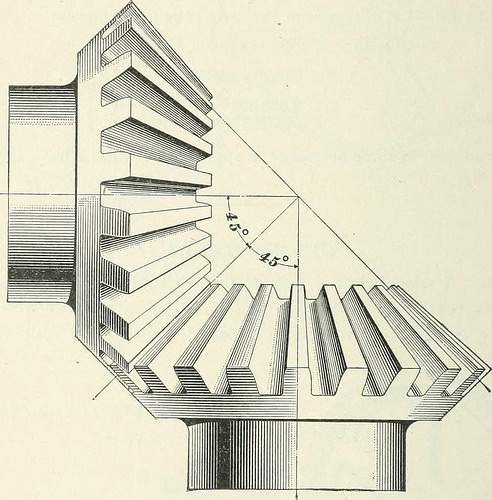
Image by Web Archive Book Pictures
Identifier: icsreferencelibr00inte
Title: I.C.S. reference library : a series of textbooks ready for the students of the International Correspondence Schools and containing in permanent type the instruction papers examination concerns, and keys utilized in their numerous courses
Year: 1904 (1900s)
Authors: International Correspondence Schools
Subjects: Bookkeeping Textile fabrics Textile factories
Publisher: Scranton : International Textbook Co.
Contributing Library: Web Archive
Digitizing Sponsor: Internet Archive
View Book Page: Book Viewer
About This Book: Catalog Entry
View All Images: All Pictures From Book
Click right here to view book online to see this illustration in context in a browseable on the web version of this book.
Text Appearing Before Image:
FIO. flOl. Fio. a. 28 MACHINE Elements. §5 the teeth are generally parallel to the axis of the wheel or toits shaft. Gears are stated to be in mesh when the teeth of two wheels,respectively, engage each and every other or interlock. 43. In Fig. 21 is shown a pair of bevel gears in mesh.Of the two wheels shown, one is smaller sized than the otherwhen both wheels of a pair of bevel gears are of the samediameter they are known as miter gears. In Fig. 22 is shown
Text Appearing After Image:
Pig. 22. a pair of miter gears in mesh. It is clear that the anglethat the teeth of these gears make with the axis of the shaftmust be 45°. 44. Of a pair of gear-wheels (either spur or bevel) havingdifferent diameters, the smaller is known as a pinion. MACHINE Components. 29 In Fig. 23 is shown a revolving s( rtw, or worm, as it iscalled, that meshes with a ^vorn^-^vlleel. It is utilised totransmit motion from a single shaftto one more at appropriate angles to it. As the worm is nothing at all elsethan a screw, each revolutiongiven to it will rotate thewheel a distance equal to thepitch of the worm consequent-ly, if there are 40 teeth in theworm-wheel, a single-threadedAvorm have to make 40 revolu-tions in order to turn the wheelonce. 45. A rack is a straightbar that has gear-teeth reduce onit. It may be regarded as part Fig. 23. of a gear-wheel in which the diameter is infinitely massive. Theteeth of racks are proportioned by the identical rules as these ofgear-wheels.
Note About Photos
Please note that these images are extracted from scanned page photos that might have been digitally enhanced for readability – coloration and appearance of these illustrations might not perfectly resemble the original work.
Image from page 843 of “Modern day mechanism, exhibiting the most current progress in machines, motors, and the transmission of energy, being a supplementary volume to Appletons’ cyclopaedia of applied mechanics” (1892)
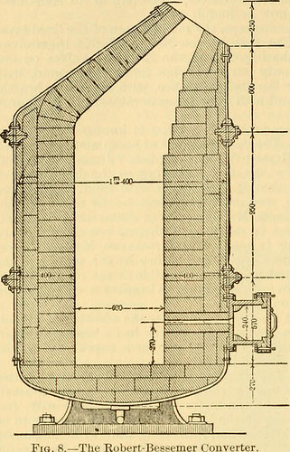
Image by Internet Archive Book Photos
Identifier: modernmechanisme00benj
Title: Contemporary mechanism, exhibiting the newest progress in machines, motors, and the transmission of energy, being a supplementary volume to Appletons’ cyclopaedia of applied mechanics
Year: 1892 (1890s)
Authors: Benjamin, Park, 1849-1922
Subjects: Mechanical engineering
Publisher: New York, D. Appleton
Contributing Library: Mugar Memorial Library, Boston University
Digitizing Sponsor: Boston University
View Book Web page: Book Viewer
About This Book: Catalog Entry
View All Pictures: All Photos From Book
Click here to view book on-line to see this illustration in context in a browseable on-line version of this book.
Text Appearing Just before Image:
lag line, and does not call for repair until it has been in use forsome six weeks. The consumption of manganese is quite low. Theoretically it is the quan-tity necessary for the formation of manganese sulphide, and in practice it has been discovered thatthis amounts to about .2 per cent. The proportion of manganese which the desulphurizedpig iron coming from the vessel need to include is best kept at about 1.five per cent, in order torender the desulphurization as full as feasible. It has been discovered that if extremely sul-phureted pig iron is poured from the blast furnace into the desulphurizing vessel, 15 to 20minutes are adequate to impact the desulphurization requisite for the steel approach. The ironin the vessel remains sufficiently fluid for a number of hours. It has been discovered quite unneces-sary to receive heat by passing and burning a present of gas above the bath of metal. Dailyanalyses for the duration of a month at Hoerde of the desulphurized metal for the fundamental procedure gave 812 STEEL, MANUFACTURE OF.
Text Appearing Soon after Image:
FiQ. eight final results as follows : phosphorus ninging from 262 to 2-93 per cent. Manganese, 1-15 to 2-97per cent. silicon, 011 to ()-31 sulphur, 0035 to 0086. the percentage of sulphur beforedesulphurization becoming OlOO to ()481. The liobert-Bessemer Converter, Fig. eight, is described in F. Lynwood Garrisons report on the Metallurgical Ai-ts at the Paris Exhi-bition (JouTunl Franklin Institute, 1^90),which see. What is claimed as novel in the converteris a combination of numerous components in a con-verter having a flat side, in which flat side areranged the tuyeres in a [)laiie horizontal tothe axis of the converter, and all in the sameplane. The tuyeres obtaining an inclinationto enable a rotary motion to be imparted tothe metal bath, and getting so disposed that bytilting the converter in the trunnions thedepth of the metal over the tuyeres can beregulated. It seems to have produced exceptional resultswherever place in operation and to be the onlyside-blown converter which is suitable for thebasic proce
Note About Pictures
Please note that these pictures are extracted from scanned web page images that may have been digitally enhanced for readability – coloration and appearance of these illustrations may not perfectly resemble the original function.
Image from web page 37 of “Steam engines, a thorough and sensible presentation of contemporary steam engine practice” (1920)
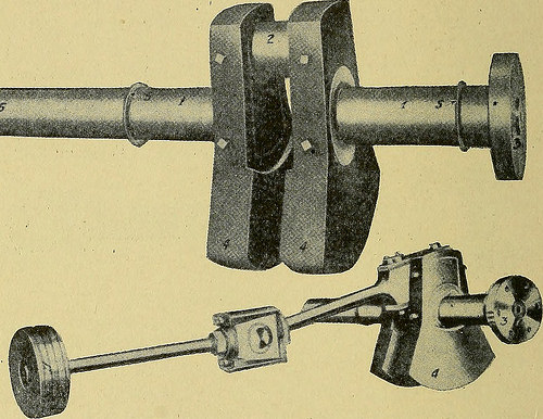
Image by World wide web Archive Book Pictures
Identifier: steamenginesthor01ludy
Title: Steam engines, a thorough and sensible presentation of modern steam engine practice
Year: 1920 (1920s)
Authors: Ludy, Llewellyn V., 1875- American Technical Society
Subjects: Steam-engines
Publisher: Chicago, American technical society
Contributing Library: The Library of Congress
Digitizing Sponsor: The Library of Congress
View Book Web page: Book Viewer
About This Book: Catalog Entry
View All Pictures: All Pictures From Book
Click here to view book on the internet to see this illustration in context in a browseable on the web version of this book.
Text Appearing Ahead of Image:
it shows quiteclearly the relation of the different components to each other. The crankshaft utilized on center-crank engines is frequently a strong steel forg-ing, which consists of the crank pin 2. Miscellaneous Parts. In order to compensate for the weight ofthe connecting rod and brasses it is necessary to place counterweightson the shaft as shown at 4, Fig. 17. These counterweights are 22 STEAM ENGINES generally heavy castings, machined to slip more than projections on thecrank shaft, and securely fastened thereto by bolts or set screws.The portion of the shaft .marked 1, Fig. 17, fits into the bearingsprovided for the primary shaft or crank shaft, the length of this bear-ing portion getting the distance among the counterweights and thecollars five. It will be noted that on one end of the shaft is situated adisk 3. At times this disk is forged as a element of the shaft, and atother occasions it is created separate and forced on by hydraulic pressure.The purpose of this disk is usually intended to provide a ready Siiui:
Text Appearing After Image:
Fig. 17 Connection of Piston, Crosshead, Connecting Rod, and Crank Shaft implies of attaching the shaft of an electric generator when a directconnected plant is feasible or desired. It may possibly be stated right here that adirect connected plant delivers numerous benefits over a belt-drivensystem. It simplifies the plant, reduces friction, gives greaterreliability, and makes feasible more power in a provided space. The projection 6 on the other finish of the shaft is the axis uponwhich the flywheel is forced and held secure by means of a key.The crank pin 2 should be of such ample proportions as to be safeagainst breakage and the heating of the pin or brasses placed upon it. STEAM ENGINES 23 All engines are not of the center-crank variety, but a lot of have aside crank, the crank being a disk or a crank arm fastened on theend of the main shaft really considerably in the very same manner as the disk S,Fig. 17. In this sort of construction the crank pin is usually a pieceseparate from the crank arm or crank disk, and is connected to i
Note About Photos
Please note that these pictures are extracted from scanned page images that may have been digitally enhanced for readability – coloration and look of these illustrations may possibly not completely resemble the original perform.