A couple of good impeller machining photos I found:
Image from page 196 of “Railway mechanical engineer” (1916)
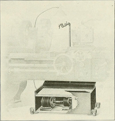
Image by Net Archive Book Photos
Identifier: railwaymechanica94newy
Title: Railway mechanical engineer
Year: 1916 (1910s)
Authors:
Subjects: Railroad engineering Engineering Railroads Railroad vehicles
Publisher: New York, N.Y. : Simmons-Boardman Pub. Co
Contributing Library: Carnegie Library of Pittsburgh
Digitizing Sponsor: Lyrasis Members and Sloan Foundation
View Book Web page: Book Viewer
About This Book: Catalog Entry
View All Pictures: All Images From Book
Click here to view book on-line to see this illustration in context in a browseable on-line version of this book.
Text Appearing Ahead of Image:
be swiftly applied to anymachine tool in the shop. Numerous machine shop tools arenot equipped with a pan and pump, simply because they are usedmostly for operating on grey iron, but occasionally the ma-chine might be used on malleable iron or steel, in which casea coolant is essential for the greatest results. In such situations, theportable unit illustrated can be utilised to good benefit.It may also be employed on machines currently offered with acoolant program, which for some cause or other is out oforder. In this emergency the transportable system shown can be quickly brought into place and production will notbe interrupted. The Fulllo pump illustrated is a total, self-containedsystem, requiring practically nothing but attaching the motor cord tothe lump socket. The total height from the floor is only14 in., which pennits its being rolled under any ordinarylathe, as shown in the illustration. Provision is produced forattaching further splash boards when required. Thepump and motor are fully covered, as a result affording
Text Appearing Following Image:
Fulflo Transportable Lubricating Unit Employed with Turret Lathe ample protection from each liquids and dust. The outfitcan be used on grinding machines as w-ell as on lathes,milling machines, drill presses, gear cutters, and so forth. Thereis only 1 moving part in the pump namely, the impeller,which has no metal contact, and for that reason cannot put on outquickly. It is packed with metallic packing which willnot cut the shaft. The bearings are effectively lubricated, andsince the shaft is hardened and ground, extended, continuedservice may be expected. MULTI GRADUATED PRECISION GRINDER It has Ijeen hard in the past to machine screw threadsurfaces with the identical accuracy obtained in machiningcylindrical, flat or spherical surfaces. On account of thisfact, it has been difficult to make master thread gages and themachine illustrated was made for this objective by thePrecision & Thread Grinder Manufacturing Organization, Phil-adelphia, Pa. It can be used in conjunction with anymachine tool and is adaptable to a range
Note About Photos
Please note that these photos are extracted from scanned page photos that might have been digitally enhanced for readability – coloration and look of these illustrations could not perfectly resemble the original function.
Image from web page 41 of “E/MJ : engineering and mining journal” (1919)
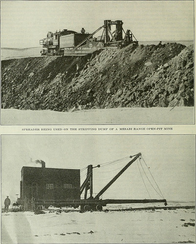
Image by Net Archive Book Photos
Identifier: emjengineeringmi108newy
Title: E/MJ : engineering and mining journal
Year: 1919 (1910s)
Authors:
Subjects: Mineral industries Engineering
Publisher: New York : McGraw-Hill
Contributing Library: Engineering – University of Toronto
Digitizing Sponsor: University of Toronto
View Book Page: Book Viewer
About This Book: Catalog Entry
View All Images: All Images From Book
Click right here to view book online to see this illustration in context in a browseable online version of this book.
Text Appearing Just before Image:
present, thelaunder method attached to the spitzkasten of every single flotationmachine is being rebuilt in such a manner that all middlingfroth and pulp are returned to a box directly in front ofthe first cell of the machine. The bottom of this box isbelow the bottom of the cell. This box is connected to thebottom of the 1st cell of the machine by a 6-in. suctionpipe. The pumping action of the impeller in the cell servesto return all froth and middling to the first cell of the ma-chine, generating every machine a separate and distinct unitand doing away with middling return elevators and theirnecessary upkeep. 22 Engineering and Mining Journal Vol. 108, No. 1 aiiiiiiiiiiiiiiiiiiiiii iiiiiiiii iiiiiiiiiiii inn inn mm mniinnn nmnnnmm mmnnmmnunnmnmmmnm i mninnn imni i i n mnnmnmnn i nnnmniiig I Modern day Stripping Gear in Minnesota | ^nnnmnniinnnMnniinnnnnniiMnninnniinnnnnninnnnnnMnniinninnnnniinnnininnninnnnninntnninnHnninninnnnnnnnnninnnnninniinninniinninninnnnnnnnnnnnnnnniinnnnninninnnjnnini^
Text Appearing Soon after Image:
MECHANICAL TRACK SHIFTER Used IN MOVING TRACK S ON STRirPIXG UUMIS Julij 5, 1919 Engineering and Mining Journal 23 ittm MW^ ^^^ m^ ^^^m BWi^p^l^^^i < . ^ /. – -^irrr w- , – H ^ *^^ •-*< – 1 • ■ . ■ •^ 1 K. . ^ ^^^^^^^Ljs ■ W ■• – ,1- V, I STEAM SHOVEL LOADING OVERBURDEN INTO 20-TD. ALT -STEEL AIR-DUMP Vehicles
Note About Photos
Please note that these pictures are extracted from scanned page pictures that may have been digitally enhanced for readability – coloration and appearance of these illustrations might not completely resemble the original perform.