A handful of good machining turbine blades pictures I found:
Image from web page 222 of “Steam turbines a sensible and theoretical treatise for engineers and students, such as a discussion of the gas turbine” (1917)
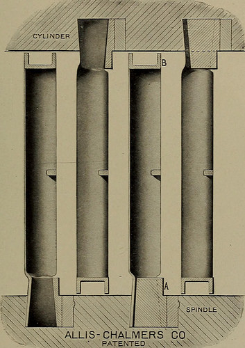
Image by Web Archive Book Images
Identifier: steamturbinespra00moye
Title: Steam turbines a sensible and theoretical treatise for engineers and students, which includes a discussion of the gas turbine
Year: 1917 (1910s)
Authors: Moyer, James Ambrose, 1875-
Subjects: Steam-turbines
Publisher: New York, Wiley
Contributing Library: The Library of Congress
Digitizing Sponsor: The Library of Congress
View Book Page: Book Viewer
About This Book: Catalog Entry
View All Pictures: All Images From Book
Click here to view book on the internet to see this illustration in context in a browseable online version of this book.
Text Appearing Prior to Image:
3Lf^O£ pL/tfCHBD dcRoa L <=?$/*so Fig. 96. Approach of Lashing Westinghouse Blades. by Fig. 96. The lashing wire, which is drawn to have a cross-section resembling a comma, binds the blades with each other firmlyenough to give adequate strength for typical service, yet, unlikea really rigid blade construction, it will yield in emergencies with out Industrial Kinds 203 seriously damaging other components of the turbine. The blades arelashed in sections 3 feet extended. Since of the peculiar shapeof the section of the lashing wire, it can be calked at the end sothat a crucial remains in the punched hole to avert the blade
Text Appearing Right after Image:
ALLIS-CHALMERS CO PATENTED , Fig. 07. Sankeys Blading for Parsons Turbines. from obtaining out of line. In many respects it is practically aseffective as a shroud ring. A variety of blading for Parsons turbines, patented by H. R.Sankey in 1903, has been applied with particular modifications inthe Allis-Chalmers and the Willans turbines. A typical illus-tration of this blading is shown in Fig. 97. It is distinguished 204 THE STEAM TURBINE principally from the usual Parsons blading by the attachment ofa U-shaped shroud ring, B, around both the moving and thestationary blades. The blades are reduce to the essential length from bars of copperalloy drawn, like wire, to a suitable shape. Right after the bladesare cut from the bar, they are formed in machine tools ofspecial style, so that at the root they have an angular dove-tail shape as illustrated in the figure, where the blades are showninserted in a suitable foundation ring, A. Following this foundationring is turned to the proper diameter, dovetail slo
Note About Images
Please note that these pictures are extracted from scanned page pictures that may possibly have been digitally enhanced for readability – coloration and look of these illustrations may possibly not completely resemble the original function.
Windmills Kinderdijk, Holland – 3619
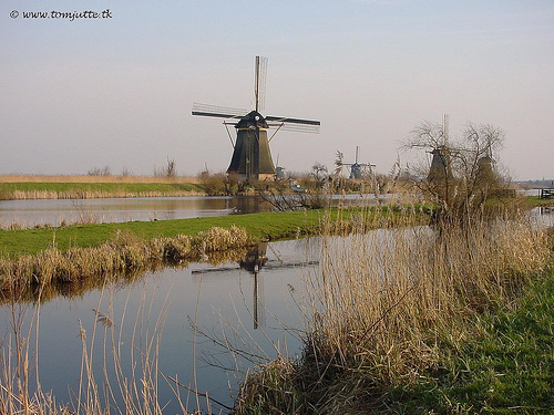
Image by HereIsTom
A windmill is a machine that is powered by the energy of the wind. It is developed to convert the energy of the wind into a lot more useful forms making use of rotating blades or sails. The term also refers to the structure it is generally built on. In a lot of Europe, windmills served originally to grind grain, although later applications incorporated pumping water and, more lately, generation of electricity. Recent electrical energy-generating versions are referred to as wind turbines.
The Kinderdijk Windmills in the Netherlands are an UNESCO Planet Heritage Website.
© www.tomjutte.tk