Verify out these turbine blade machining pictures:
Image from web page 313 of “Stationary steam engines, easy and compound particularly as adapted to light and power plants” (1902)
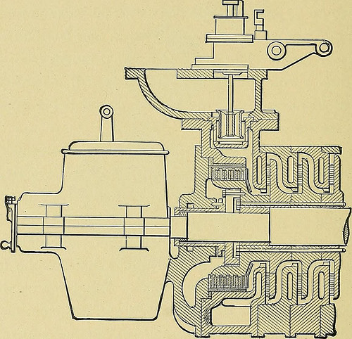
Image by Net Archive Book Images
Identifier: stationarysteame03thur
Title: Stationary steam engines, easy and compound particularly as adapted to light and energy plants
Year: 1902 (1900s)
Authors: Thurston, Robert H[enry], 1839-1903. [from old catalog]
Subjects: Steam-engines
Publisher: New York, J. Wiley & sons London, Chapman & Hall, restricted
Contributing Library: The Library of Congress
Digitizing Sponsor: The Library of Congress
View Book Web page: Book Viewer
About This Book: Catalog Entry
View All Pictures: All Photos From Book
Click here to view book on-line to see this illustration in context in a browseable on-line version of this book.
Text Appearing Just before Image:
his sort of machine is that familiar to thehydraulic engineer, and the speeds of orifice for maximumefficiency are nicely-known to be infinite in the Hero class ofturbine and around 1-half the final velocity of flowin the guide-blade turbine. Since these speeds are imprac-ticable in their use, a specific loss of power is hence inevita-ble. In compensation for this loss, in the steam-turbine, isthe truth that it is not subject to that fluctuation of tempera-ture of parts exposed to make contact with with the steam which re-sults in large wastes by cylinder-condensation in the commonforms of steam-engine. In this way a acquire of from 25 to50 per cent, as compared with the latter, is to be countedupon. 276 STEAM ENGINES FOR The Dow turbine, as built for operate in connection withthe Howell torpedo, gives an average of about 11 horse-power in coming up to speed in standard working, at. 60pounds steam-pressure, and weighs from 100 to 150 pounds,or not far from 13 pounds per horse-energy. Its fly-wheel
Text Appearing Right after Image:
A Sectional View of the Parsons Turbine. rim attains a speed of nearly 7 miles an hour at ten,000revolutions per minute. The designer estimates its powerat 150 pounds steam-stress and the identical speed at 40horse-power, or 1 horse-power to three.75 pounds weight, andstates that this may possibly be nonetheless additional reduced to the extraor-dinary minimum of 2 pounds weight per horse-energy, a I, Electrical World, April i8, i8gi. ELECTRIC LIGHTING PLANTS. 277 figure properly inside the estimated allowable maximum for usein aeronautic perform. The steam-turbine of Parsons is an engine consisting oi aseries of turbines, the different pairs of guides and wh&elsbeing so placed that the fluid passes successively from owepair to the next. Of the two forms, radial and axial flow,only the latter have been utilized here. IVo series of cylin-drical turbines are utilised, arranged symmetrically to the rightand left of the central steam-inlet, the exhaust taking placefrom the two ends. In this manner a balance is obtained,and
Note About Images
Please note that these pictures are extracted from scanned web page pictures that may possibly have been digitally enhanced for readability – coloration and appearance of these illustrations could not perfectly resemble the original work.
Image from web page 316 of “Heat engineering a text book of applied thermodynamics for engineers and students in technical schools” (1915)
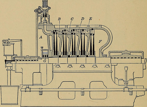
Image by Internet Archive Book Pictures
Identifier: heatengineeringt00gree
Title: Heat engineering a text book of applied thermodynamics for engineers and students in technical schools
Year: 1915 (1910s)
Authors: Greene, Arthur Maurice, 1872- [from old catalog]
Subjects: Thermodynamics
Publisher: New York [etc.] McGraw-Hill book business, inc.
Contributing Library: The Library of Congress
Digitizing Sponsor: The Library of Congress
View Book Page: Book Viewer
About This Book: Catalog Entry
View All Photos: All Photos From Book
Click here to view book online to see this illustration in context in a browseable on the web version of this book.
Text Appearing Prior to Image:
chest. The velocity is utilizedon a single set of blades. To improve the power of the machine anumber of nozzles are utilised. The angle of the nozzle relative tothe plane of the blade is produced as small as feasible, as shown inFig. 150, so that the efficiency which is proportional to cos2 ais as huge as feasible. The peripheral speed of the wheel is quite 302 HEAT ENGINEERING great. wa is equal to 3820 ft. per second if the drop in the nozzleis from 150.1 lbs. gauge to six lbs. absolute. The speed of the wheelfor a value of / of .95 and cos a = .9 would be Wh=zy2X o.9 X 3820 = 1719 ft. per sec. This would mean 16,400 r.p.m. for a radius to the blades of 1 ft.The pressure drop for the axial distances of nozzle and blade andthe absolute velocity modifications are shown in Fig. 151. This figuregives a section through the axis and 1 parallel to the axis throughthe blades and nozzle. The Curtis turbine is shown in Fig. 152. In this steam entersthe nozzle at A and is discharged against moving vanes. The
Text Appearing Right after Image:
Fig. 152.—Section by means of horizontal Curtis turbine. discharge from these moving vanes is guided by stationary vanesto yet another set of movable vanes, and soon after discharge from theseit is taken to yet another set of nozzles B and discharges into a secondset of vanes. In the figure shown there are 5 sets of nozzles,A, B, C, D, and E, and to each of these there are two movableand one fixed set of vanes. The pressure drop requires location infive stages, and there is no drop in stress over the blades.The exhaust space F is connected to the condenser. This actionis much better shown in Fig. 153 in which a section via the axis STEAM NOZZLES, INJECTORS, STEAM TURBINES 303 and one particular parallel to the axis of a two-stage turbine are shown sideby side following the strategy employed by Moyer. In the figure thepressure is seen to be constant across the sets of vanes, the dropin stress and consequently the obtain in velocity taking placein the nozzles. The turbine is for that reason of the impulse sort.In some cases t
Note About Pictures
Please note that these photos are extracted from scanned page pictures that might have been digitally enhanced for readability – coloration and appearance of these illustrations might not completely resemble the original function.