Verify out these turbine blade machining pictures:
Image from web page 74 of “Electrical globe” (1883)
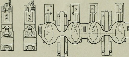
Image by Internet Archive Book Photos
Identifier: electricalworld43newy
Title: Electrical globe
Year: 1883 (1880s)
Authors:
Subjects: Electrical engineering
Publisher: [New York McGraw-Hill Pub. Co., and so on.]
Contributing Library: Engineering – University of Toronto
Digitizing Sponsor: University of Toronto
View Book Page: Book Viewer
About This Book: Catalog Entry
View All Photos: All Photos From Book
Click here to view book online to see this illustration in context in a browseable on-line version of this book.
Text Appearing Ahead of Image:
. In shaft construction great rigidity has been secured with minimumuse of metal. A central steel quill carries the complete rotating parts,both blades and balance pistons. Hollow forged steel ends are 6o ELECTRICAL World and ENGINEER. Vol. XLIII, No. i. forced into the two ends of this quill beneath hydraulic pressure, andare, in addition, secured by arrowhead links. High-stress steamis conveyed to all parts of this quill structure in such a manner asto eradicate stresses and consequent distortion due to highly super-heated steam. Power is transmitted to the generator shaft by means of a flexiblecoupling which is housed partly by the turbine and partly by thegenerator inboard journal. The coupling is split at the junction ofthe two shafts, so that by removing 1 bearing cap and the couplingbolts, either section of the unit could be lifted out without having disturbingthe adjustment of the remaining section. In the smaller sizes theengagement surfaces of the coupling consist of the squared or hexa-
Text Appearing Soon after Image:
FIG. three.—COMP.-RATIVE SIZES OF TWO TURBINES AND TWO RECIPROCATINGENGINES. gonal ends of the shafts, but in the bigger machines a crow-foot sleeveis keyed to each shaft and the power is transmitted by an outsidequill engaging the crow-feet. Therefore great flexibility is secured, to-gether w ith the greatest facility in dismantling. The journals in the larger machines are of the strong self-aligningtype, equivalent to that employed in generators and cross-compoundengines. The departure from the familiar oil-cushioned journal em-ployed in the modest machines is occasioned by the speed reductionsecured. The journal shells are babbitt-lined and are split horizon-tally, the two halves being united by bolts with shim adjustment. inch. After set, these adjustments are permanent and do not requirefrequent taking up. Steam enters the turbine successively via an automatic fast-closing throttle, hand throttle, strainer and the principal admission valve.A circular port surrounding the entrance to the init
Note About Photos
Please note that these pictures are extracted from scanned web page images that could have been digitally enhanced for readability – coloration and look of these illustrations could not perfectly resemble the original work.