A couple of good 7 axis machining images I found:
Image from web page 464 of “Contemporary mechanism, exhibiting the most current progress in machines, motors, and the transmission of power, getting a supplementary volume to Appletons’ cyclopaedia of applied mechanics” (1892)
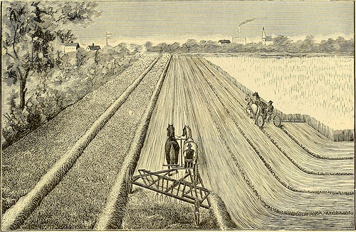
Image by Internet Archive Book Images
Identifier: modernmechanisme00benj
Title: Modern day mechanism, exhibiting the most recent progress in machines, motors, and the transmission of power, getting a supplementary volume to Appletons’ cyclopaedia of applied mechanics
Year: 1892 (1890s)
Authors: Benjamin, Park, 1849-1922
Subjects: Mechanical engineering
Publisher: New York, D. Appleton
Contributing Library: Mugar Memorial Library, Boston University
Digitizing Sponsor: Boston University
View Book Page: Book Viewer
About This Book: Catalog Entry
View All Pictures: All Photos From Book
Click here to view book on the internet to see this illustration in context in a browseable on the internet version of this book.
Text Appearing Before Image:
place, and rebolting them united midway of the hounds. An additional single-tree and a false pole-lip are .supplied. Therefore the rake is rendered offered for either onehorse or a span, and in an emergency the mower-group might be shifted to the rake. In manydistricts farinersrarelyu.se a single hor.se for field-work—which makes this arrangement adesirable convenience, obviating the require of a specific single-work harness for tiie hay-raking.7/ie Chamberlim Side-Delirery Hay-Rake is shown in Fig. four. It rides on 3 wheels,the rear one a caster, providing triangular help and maintaining the operating axis parallel HEATERS, FEED-WATER. 443 with the surface of the ground at appropriate height. A single of the two forward wheels is connectedby a chain-drive with a cross-shaft geared by cogs to an oblique intermediate shaft, chain-geared in turn to the crank-shaft, from which a set of four tedder-heads get motion.Each tedder-head is armed with 3 tines. The crank-shaft becoming disposed at an angle of
Text Appearing Following Image:
Fig. 4.—Side-delivery hay-rake. about 45^ from the line of travel, the tedders successively rake and pitch the swath-hay towardand lastly beyond a single side of the machine, constantly, into a loose, effectively-ventilated wind-row, without having rolling or compressing it. A strip some ten ft. wide is windrowed with no anymanipulation frorathe driver. Two horses are employed. As it does not traverse the surfaceactually occupied by the windrows, there is a saving of distance to be traversed in any givenfield. This class of rake is specially advantageous for use in connection with the automatichay-loaders of the class described in this post. In the Keystone Side-Delivery Hay-Rake the axle is the main driving-shaft bevel-geared to a shaft with its axis in the line of travel. The latter shaft carries chain-wheelsdriving two rake-chains, which serially draw a gang of rakes, armed with curved teeth, trans-versely via the stubble, and transfer the mown hay from the swath into a raked windrowat on
Note About Images
Please note that these pictures are extracted from scanned web page photos that may possibly have been digitally enhanced for readability – coloration and look of these illustrations might not perfectly resemble the original perform.