Some cool all axis machining pictures:
Image from page 144 of “Machine design and style” (1906)
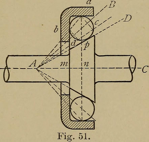
Image by World wide web Archive Book Pictures
Identifier: machinedesign02benj
Title: Machine style
Year: 1906 (1900s)
Authors: Benjamin, Charles H[enry], 1856- [from old catalog]
Subjects: Machine style
Publisher: New York, H. Holt and firm
Contributing Library: The Library of Congress
Digitizing Sponsor: The Library of Congress
View Book Page: Book Viewer
About This Book: Catalog Entry
View All Pictures: All Photos From Book
Click here to view book online to see this illustration in context in a browseable on-line version of this book.
Text Appearing Before Image:
farmentioned have nomeans of adjustmentfor wear. Conicalbearings, or these inwhich the axes of theballs meet in a com-mon point, supplythis deficiency. In designing this class of bearings,either for side or end thrust, the inclination of theaxis is assumed according to the obliquity desired andthe points of speak to are then so located that thereshall be no slipping. Fig. 51 illustrates a widespread kind of adjustable orcone bearing and shows the approach of designing athree point make contact with. A Cis the axis of the cone,whilst the shaded area is asection of the cup, socalled. Let a and b betwo points of get in touch with be-tween ball and cup. Drawthe line a b and produceto reduce axis in A. Throughthe center of ball drawthe line A B then willthis be the axis of rotation of the ball and a c,bdwill be the projections of two circles of rotation. Asthe radii of these circles have the exact same ratio as the radiiof revolution a n, b m, there will be no slipping andthe ball will roll as a cone inside an additional cone. The
Text Appearing Following Image:
120 MACHINE Style. precise location of the third point of contact is notmaterial. If it were at c, too considerably stress wouldcome on the cup at b if at d there would be an excessof pressure at a, hut the rolling would be right ineither case. A handy approach is to find p bydrawing A D tangent to ball circle as shown. It isrecommended nonetheless that the two opposing surfacesat p and & or a need to make with each and every other an angleof not less than 25 deg. to keep away from sticking of the ball. To convert the bearing just shown to 4 pointcontact, it would only be required to alter the onecone into two cones tangent to the ball at c and d. To minimize it to two point make contact with the points a and bare brought with each other to a point opposite p. As in thislast case the ball would not be confined to a definitepath it is customary to make a single or each surfaces con-cave conoids with a radius about three fourths thediameter of the ball. See Fig. 52. 59. Step-Bearings. Thesame principles apply asin the prec
Note About Images
Please note that these pictures are extracted from scanned page images that could have been digitally enhanced for readability – coloration and look of these illustrations might not completely resemble the original perform.
Image from web page 207 of “Machine design” (1906)
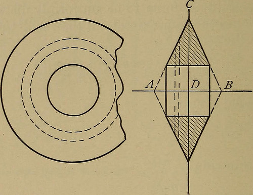
Image by World wide web Archive Book Photos
Identifier: machinedesign02benj
Title: Machine style
Year: 1906 (1900s)
Authors: Benjamin, Charles H[enry], 1856- [from old catalog]
Subjects: Machine style
Publisher: New York, H. Holt and business
Contributing Library: The Library of Congress
Digitizing Sponsor: The Library of Congress
View Book Page: Book Viewer
About This Book: Catalog Entry
View All Pictures: All Photos From Book
Click right here to view book online to see this illustration in context in a browseable on the internet version of this book.
Text Appearing Just before Image:
sume the stress on the location at AB dueto the centrifugal force to be uniformly distributed :(and here lies the approximation) then will the tensilestress on the section be e C ±wvD2 + Dd+d2) ,lnAv S=(D=Wt= gU * (1°0) For a strong disc : s^Jf- (101) For a thin ring : S^J^f (102) on the identical as in equation (89). If the metal be completely elastic, Stodolas formulas give S= as the anxiety close to the center when d ap-proaches 0— or more than twice the value provided in(101). In view of the imperfect elasticity of the metalsused the true value will probably be amongst these two.This value ought to be determined by experiment. 180 MACHINE Design and style. 88. Conical Discs. Let Fig. 81 represent a ringwhose thickness varies uniformly from the inner to theouter circumference and whose dimensions are as fol-lows : D=outer diameter in inches. d=inner diameter b=breadth of ring at inner circumference. m=tangent of angle of slant CAD. Then m D-d or b D-d b m By cutting the ring into slices perpendicular to the
Text Appearing Soon after Image:
Fig. 81. axis, discovering the centrifugal force for each and every slice andthen integrating between D and cZ, the centrifugalforce of the half-ring is located to be : c_wv2(Di+Zdi-4:Dd*)~~ mgD2 (103) The location on the line A B to resist the centrifugal %tf-±Dd*) (104) f . (D-d)two A o ZwifiD* force is : ^ and S= ^-rw/ 2m gDD—d) BURSTING SPEEDS. 181 Whend= : SJ^- (105) 9 or a stress one-half that of a plain flat disc. 89. Discs with Logarithmic Profile. A form ofdisc at times utilized for steam turbines consists of asolid of revolution generated by a curve of theequation y=a log I revolving about the x—axis. Mr. Levin investigates two curves of this character : y=log x and y=two log -^ and finds the stresses to be respectively : When a=b S = 1.five^ (106) 9 When a=ib S=l.tf^ (107) The basic equation for S in this case is : s==mwvl.^. (108) and in deriving the formulas (106) and (107) D is as-sumed as 8a and as da respectively. 90. Bursting Speeds. It will be seen that all theformulas for centrifugal s
Note About Pictures
Please note that these photos are extracted from scanned web page images that may possibly have been digitally enhanced for readability – coloration and look of these illustrations might not completely resemble the original operate.
Image from web page 149 of “Machine design and style” (1906)
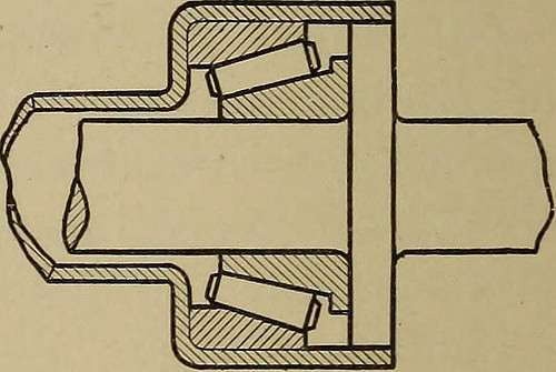
Image by World wide web Archive Book Images
Identifier: machinedesign02benj
Title: Machine style
Year: 1906 (1900s)
Authors: Benjamin, Charles H[enry], 1856- [from old catalog]
Subjects: Machine style
Publisher: New York, H. Holt and company
Contributing Library: The Library of Congress
Digitizing Sponsor: The Library of Congress
View Book Page: Book Viewer
About This Book: Catalog Entry
View All Pictures: All Images From Book
Click right here to view book online to see this illustration in context in a browseable on the internet version of this book.
Text Appearing Ahead of Image:
rm of guide entails nn Fig. 55. B ) sliding friction. The cage normally used is a cylin-drical sleeve getting longitudinal slots which holdthe rollers loosely and avoid their receiving out ofplace either sideways or endways. The use of balls or convex washers at the ends of therollers has been attempted with some degree of achievement.See Fig. 55. Massive rollers have been turned smallerat the ends and the bearings then formed allowed toturn in holes bored in revolving collars. These collarsmust be so fastened or – geared collectively as to turn inunison. 63. Grant Roller Bearing. The Grant roller is conicaland types an intermediate between the ball and thecylindrical roller getting someof the positive aspects of every.The principle is considerably thesame as in the adjustable ballbearing, Fig. 52, rolling conesbeing substituted for balls,Fig. 56. The inner cone turnsloose on the spindle. Theconical rollers are held in posi-tion by rings at each and every end, although the outer or hollowcone ring is adjustable along the axis.
Text Appearing Following Image:
Fig. 56. HYATT ROLLERS. 125 Two sets of cones are utilized on a bearing, 1 at eachend to neutralize the end thrust, the exact same as with ballbearings. 64. Hyatt Rollers. The tendency of the rollers toget out of alignment has been already noticed. TheHyatt roller is intended by its flexibility to secureuniform stress and wear beneath such circumstances. Itconsists of a flat strip of steel wound spirally abouta mandrel so as to type a continuous hollow cylinder.It is correct in form and comparatively rigid against com-pression, but possesses adequate flexibility to adaptitself to slight changes of bearing surface. Experiments made by the Franklin Institute showthat the Hyatt roller possesses a fantastic advantage inefficiency more than the solid roller. Testing § inch rollers in between flat plates beneath loadsincreasing to 550 lb. per linear inch of roller developedco-efficients of friction for the Hyatt roller from 23 to51 per cent, less than for the strong roller. Subsequentexamination of the plates showed
Note About Images
Please note that these pictures are extracted from scanned web page pictures that might have been digitally enhanced for readability – coloration and appearance of these illustrations could not completely resemble the original operate.