Some cool machining impeller services images:
Image from page 283 of “Railway mechanical engineer” (1916)
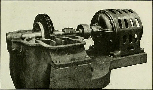
Image by Internet Archive Book Images
Identifier: railwaymechanica90newy
Title: Railway mechanical engineer
Year: 1916 (1910s)
Authors:
Subjects: Railroad engineering Engineering Railroads Railroad cars
Publisher: New York, N.Y. : Simmons-Boardman Pub. Co
Contributing Library: Carnegie Library of Pittsburgh
Digitizing Sponsor: Lyrasis Members and Sloan Foundation
View Book Page: Book Viewer
About This Book: Catalog Entry
View All Images: All Images From Book
Click here to view book online to see this illustration in context in a browseable online version of this book.
Text Appearing Before Image:
Pneumatic Machine for Light Punching and Riveting air pressure and will satisfactorily drive )■■% in. rivets cold.A specially designed cushion in the top head prevents shockafter the punch has passed through the plate. The frame, themain lever and the plunger are steel castings, the cylinder 266 RAILWAY MECHANICAL ENGINEER Vol. 90, No. 5 parts being chiefly of cast iron. The machine weighs 225 lb.and consumes 1.26 cu. ft. of free air per stroke. It is manu-factured by the Hanna Engineering Works, and distributedthrough the Vulcan Engineering Sales Company, Chicago. TURBO-BLOWER The Ingersoll-Rand Company, New York, has added toits turbo-compressors and blowers a low pressure machinefor volumes of from 3,000 to 35,000 cu. ft. per minute atfrom 1 to 2)A lb. pressure. These are particularly adaptedto such service as foundry cupola blowing, atomizing oil for
Text Appearing After Image:
Low Pressure Type Turbo-Blower with Upper Casing Removed.Showing Double Flow Enclosed Impeller oil burners, supplying blast to heating and annealing fur-naces of various kinds, blowing air for water gas generators,pneumatic conveying and ventilating. They are of the singlestage, double flow type and are furnished either electricmotor, steam turbine or water wheel driven. Electric drive is
Note About Images
Please note that these images are extracted from scanned page images that may have been digitally enhanced for readability – coloration and appearance of these illustrations may not perfectly resemble the original work.
Image from page 389 of “Railway mechanical engineer” (1916)
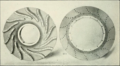
Image by Internet Archive Book Images
Identifier: railwaymechanica89newy
Title: Railway mechanical engineer
Year: 1916 (1910s)
Authors:
Subjects: Railroad engineering Engineering Railroads Railroad cars
Publisher: New York, N.Y. : Simmons-Boardman Pub. Co
Contributing Library: Carnegie Library of Pittsburgh
Digitizing Sponsor: Lyrasis Members and Sloan Foundation
View Book Page: Book Viewer
About This Book: Catalog Entry
View All Images: All Images From Book
Click here to view book online to see this illustration in context in a browseable online version of this book.
Text Appearing Before Image:
ssure in adirection opposite to that acting upon the impeller disk, whilethe chamber upcn the opposite side of the balancing disk is con-nected to the suction inlet, thus completely neutralizing {he un-balanced pressure on all of the wheels. As in the case of single-stage blowers, the head-delivery char-acteristic can be varied considerably to meet different require-ments. Generally where compressed air is used in tools, a fairlyconstant pressure over a wide range of delivery is desired. Thecappcities in such cases range between 2,000 and 10.000 cu. ft.per nun., and the pressures from 75 to 120 lb. per sq. in. Less than 2,000 cu. ft. per min, is usually not practicable. The largermachines for these pressures or machines which must run atmotor speeds, are usually built in two sections, with separateshafts and housings, the speeds available with electric motors ofthese sizes requiring either a compressor with a large numberof stages and several housings, or the use of a step-up gear, by
Text Appearing After Image:
Impeller Disc and Side Plate of Multi-Stage Air CompressorShowing IVIethod of Attaching Vanes which the coinpresjor can l,e ■ pcrated al -l.OGO to 5,000 r. p. m.Where either strictly constant head (^r strictly constant rateof delivery is required, speed variatiun or throttling of thesuction is reported to. SAND BLASTING STEEL CAKS h has been a ditiicult problem in connection with the use ofsteel cars to clean the exterior in a satisfactory manner beforepainting. The use of acids for this i)urpose is not entirely satis-factory and this method is also dangerous for the workmen. Tlie matter of cleaning has assumed increased importancewith the general advent of the steel passenger car, and wheresand blasting has been adopted it seems to have been productiveof remarkably good results. The engravings show side elevation and sectional views of asand blast installation which is in successful operation on a largesystem operating a great many steel cars in both passenger andfreight service. T
Note About Images
Please note that these images are extracted from scanned page images that may have been digitally enhanced for readability – coloration and appearance of these illustrations may not perfectly resemble the original work.
Image from page 283 of “Railway mechanical engineer” (1916)

Image by Internet Archive Book Images
Identifier: railwaymechanica90newy
Title: Railway mechanical engineer
Year: 1916 (1910s)
Authors:
Subjects: Railroad engineering Engineering Railroads Railroad cars
Publisher: New York, N.Y. : Simmons-Boardman Pub. Co
Contributing Library: Carnegie Library of Pittsburgh
Digitizing Sponsor: Lyrasis Members and Sloan Foundation
View Book Page: Book Viewer
About This Book: Catalog Entry
View All Images: All Images From Book
Click here to view book online to see this illustration in context in a browseable online version of this book.
Text Appearing Before Image:
Low Pressure Type Turbo-Blower with Upper Casing Removed.Showing Double Flow Enclosed Impeller oil burners, supplying blast to heating and annealing fur-naces of various kinds, blowing air for water gas generators,pneumatic conveying and ventilating. They are of the singlestage, double flow type and are furnished either electricmotor, steam turbine or water wheel driven. Electric drive is
Text Appearing After Image:
Ingersoll-Rand Low Pressure Type Turbo-Blower generally employed for the classes of service mentioned andin the case of the I-R turbo-blower, the high operative speedpermits direct coupling to the motor. This motor-drivenblower maintains constant pressure while delivering any volume from zero to maximum demand and proportionatelyvarying the electrical horsepower input. These blowers embody the four bearing construction fea-tured in all turbo machines of this make. The casing is hori-zontally split for ease in installation and subsequent inspec-tion. The assembled casing is doweled and bolted to a heavysub-base which ordinarily serves for both blower and drivingelement. The I-R machine occupies small floor space and itslack of vibration in operation obviates the necessity forfoundation bolting. The impeller is of the enclosed doubleflow type, which is claimed to secure the highest efficiency.The wheel is machined from a solid, special steel forging.The vanes and covers are of pressed s
Note About Images
Please note that these images are extracted from scanned page images that may have been digitally enhanced for readability – coloration and appearance of these illustrations may not perfectly resemble the original work.