Check out these machining turbine rotors images:
Image from page 309 of “The Locomotive” (1867)
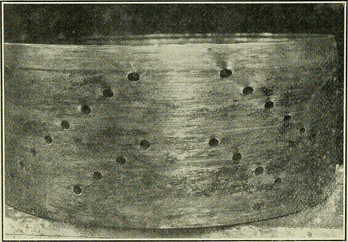
Image by Internet Archive Book Images
Identifier: locomotive34hart
Title: The Locomotive
Year: 1867 (1860s)
Authors: Hartford Steam Boiler Inspection and Insurance Firm
Subjects: Locomotives Steam-boiler explosions
Publisher: Hartford, Ct. : Hartford Steam Boiler Inspection and Insurance Co
Contributing Library: Carnegie Library of Pittsburgh
Digitizing Sponsor: Lyrasis Members and Sloan Foundation
View Book Page: Book Viewer
About This Book: Catalog Entry
View All Photos: All Pictures From Book
Click right here to view book on the web to see this illustration in context in a browseable on the internet version of this book.
Text Appearing Just before Image:
licy. The direct cause ofthe accident is not clear,but the proof in-dicates that in someway the machine lost itselectrical load. An ex-amination of the wreck-ed generator failed toshow any indicators of burn-ing or other electricaldisturbance, it appar-ently becoming electricallydead ahead of disruption G- r occurred. Evidence of overspeed, nevertheless was apparent and indicatedthat, when the turbine lost its load, each the governor and emergencystop failed to function speedily enough and the machine ran away,despite the fact that a current inspection had indicated that these valves had been func-tioning properly. The accompanyingpictures show veryplainly some of the un-usual characteristics of thisaccident. The coverpage illustration is aview of the generatorend of the machine andgives an notion of thecompleteness of thewreck. The rotor dis-rupted, gripped thestator windings andcaused them to turnwith it to a particular extent, thereby rupturing the entire generatorframe. The rotor can be noticed firmlv wedged inside the stator
Text Appearing Soon after Image:
i924.] Till: LOCOMOTIVE. 35 windings. Figure I is a view of the rotor right after it had been re-moved from the wreckage. It will be observed that torsional forcehas wrenched the shaft so that the slots are no longer parallel to theaxis, and that centrifugal force has torn away a large section of thelaminated discs of which the outer component of the rotor was composed. Inthe background of this image can be seen the ruptured frame ofanother machine. Figure two is a view of an end shield of the field winding, and isof interest as giving evidence of excessive overspeed. This ring islyi thick and is drilled in diagonal rows of l/2 holes for ventilatingpurposes. As can be observed in the image, these holes are considerablyelongated circumferencially as a outcome of the hoop tension created.The other finish shield, shown in the foreground of Figure 1, disruptedthrough a line of holes and flattened out. The turbine itself did not explode, but the shaft was bent, theblades being seriously damaged by rubbin
Note About Pictures
Please note that these pictures are extracted from scanned page pictures that may have been digitally enhanced for readability – coloration and look of these illustrations might not perfectly resemble the original function.
Image from web page 1225 of “Electric railway journal” (1908)
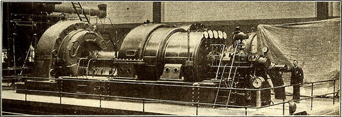
Image by Web Archive Book Images
Identifier: electricrailway341909newy
Title: Electric railway journal
Year: 1908 (1900s)
Authors:
Subjects: Electric railroads
Publisher: [New York] McGraw Hill Pub. Co
Contributing Library: Smithsonian Libraries
Digitizing Sponsor: Smithsonian Libraries
View Book Page: Book Viewer
About This Book: Catalog Entry
View All Pictures: All Photos From Book
Click right here to view book on-line to see this illustration in context in a browseable online version of this book.
Text Appearing Ahead of Image:
the mean possible getting 6500volts. The turbine and generator are connected by a gearedflexible coupling. The alternator is ventilated by a fan,which draws air by means of a duct through a particular filter-ing arrangement situated in a chamber outside. Twenty- 120.000 21 one hundred,000 g <,„ 1 a h 80.000 « 16 60,000 two § 40,000 eight 20,000 ° 5,7120 E B ,A jU _A ,. D F F 60 F20| 1000 20U0 3000 4000 5000 6000 7000 SuOQKilowatts of Output. A. Howden Consumption Curve, 28 Vac. Total Temp, of Steam,523° F. B. 27 Vac.483° F. D. Howden Thermo-dynamic Efficiency Curve. E. Total Water Consumption. F. No Load Consumption. Curves of Steam Consumption a single thousand cubic feet of air per minute are delivered ata stress of 2l/2 in. of water to the rotor, returningthrough the stator frame to an additional duct, which carries itout of the developing. The condensing plant has been sup-plied by Richardson, Westgarth & Firm, Ltd., and con-cists of a Contraflo condenser with a surface of ten,500 sq.
Text Appearing Following Image:
Basic View of 6000-Kw Turbine as Installed in the Manchester Energy Station A speed-regulating gear is fitted to the throttle valve,which is actuated either by hand or by the little electricmotor shown in the basic view of the machine. Thespeed of the machine is 1000 r.p.m. A supplementarygovernor js provided, which shuts down the supply ofsteam must the speed rise to 10 per cent above thenormal. This governor acts by means of a trip gear, andenables I lie main cease valve to be immediately closed by apowerful spring, the impact of the valve on its seatingbeing cushioned by an air piston. A noteworthy featurein the operating .so far has been the quite slight leakage ofair into the turbine casing via the glands, thus fa-cilitating the upkeep of a high vacuum even whenusing high temperature of circulating water. ft. There is one particular set of electrically driven 3-throwEdwards air pumps. The water has a static head of 30 ft.,and is drawn, and not forced, by means of the condenser, thepu
Note About Images
Please note that these pictures are extracted from scanned page pictures that may possibly have been digitally enhanced for readability – coloration and look of these illustrations could not completely resemble the original operate.