Verify out these machining turbine rotors photos:
Image from page 174 of “The Locomotive” (1867)
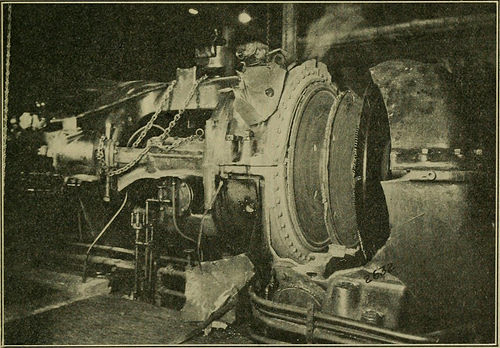
Image by Net Archive Book Photos
Identifier: locomotive36hart
Title: The Locomotive
Year: 1867 (1860s)
Authors: Hartford Steam Boiler Inspection and Insurance coverage Firm
Subjects: Locomotives Steam-boiler explosions
Publisher: Hartford, Ct. : Hartford Steam Boiler Inspection and Insurance coverage Co
Contributing Library: Carnegie Library of Pittsburgh
Digitizing Sponsor: Lyrasis Members and Sloan Foundation
View Book Page: Book Viewer
About This Book: Catalog Entry
View All Images: All Images From Book
Click here to view book on the web to see this illustration in context in a browseable on the web version of this book.
Text Appearing Before Image:
Devoted to Energy Plant Protection Published Qu^uiterly Vol. XXXVI HARTFORD, CONN., APRIL, 1927. No. 6. COPYRIGHT, 1927, BY THE HARTFORD STEAM BOILER INSPECTION AND Insurance coverage CO.
Text Appearing Soon after Image:
Steam Turbine Explosion at Chillicothe, Ohio. THERE IS Worthwhile Information FOR YOUR ENGINEER IN THIS MAGAZINE. PLEASE LET HIM SEE IT. 162 THE LOCOMOTIVE. [April, Steam Turbine Explosion at Chillioothe, Ohio. THE disruption of a disk in the third stage on the rotor of a three,000kw. turbine Friday morning, August 20th, 1926, at the plant ofthe Mead Pulp and Paper Organization, Chillicothe, Ohio, resulted ina property loss of ,000 not counting the use and occupancy loss.Two guys have been injured, but fortunately their injuries had been not seriousdespite the fact that 1 of the males at the time of the accident wasstanding beside the machine that exploded. A view of the turbine afterthe explosion is shown on the front cover. The home harm was heavy but was confined practically entirelyto the turbo-generator unit itself. The steam finish of the unit was acomplete loss, and in addition considerable harm was accomplished to theelectric generator. The bell end of the generator casing was cracked,the shaft sprung,
Note About Photos
Please note that these photos are extracted from scanned page photos that may have been digitally enhanced for readability – coloration and appearance of these illustrations may not completely resemble the original function.
Image from web page 312 of “Railway Times” (1908)
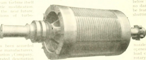
Image by Net Archive Book Pictures
Identifier: railwaytimes101londuoft
Title: Railway Times
Year: 1908 (1900s)
Authors:
Subjects:
Publisher: London
Contributing Library: Gerstein – University of Toronto
Digitizing Sponsor: MSN
View Book Web page: Book Viewer
About This Book: Catalog Entry
View All Pictures: All Images From Book
Click right here to view book on the internet to see this illustration in context in a browseable on the web version of this book.
Text Appearing Prior to Image:
5.000 KW. Curll* TurOo.Altamator. frvjr.lr.l j« iiijirfvr.|r.| «. l4r .»* Iar|.:r M/r^ .in| I.., ,,, vi ,-. • ,(.r. il .-1 t.M%lnifl rnKKM^t .llf llllil f(r |>i>wrt« llw liiiliUM iS .**».<■». <!■ •tiitiiii% at inr^cnl li|il« !!»it Ult ( kliCSlM .H>lvfc tu lu(
Text Appearing Following Image:
r«w.Mt<T.^n1f Aprii. six, T912.] THE R.TT,WAV Occasions. 361 in the baseplate of the turbine into which the ovcrllow fromall the bearings is discharged. On its way to the pump, theoil pa.sscs by means of a patent strainer which is arranged in sucli■J. way that the straiuins medium can l)c clianfjcd whilst theturbine is running with out stoppin the How of oil. On lea in,the pump the oil passes by way of a cooler which takes the formof a little surface condenser, l-dr beginning up, a tiny duplexsteam pump is litted to operate in parallel with the principal oilpump. The generator has a typical rating of six,250 kva. and delivcnsthis power in the kind of 2-phase, 50-cycIe present at two,200volts, per phase. The rotor has four poles anfl, of course, thespeed is the very same as that of the turbine, namely 1,500 r.p.m.The overload capacity, which the machine is capable of carry-ing for two hours, is 7.800 kva. or 25 per cent, above thenormal rating. The principal function of interest in a machine of this capa
Note About Photos
Please note that these photos are extracted from scanned page images that may possibly have been digitally enhanced for readability – coloration and look of these illustrations could not completely resemble the original function.
Image from page 214 of “Cyclopedia of applied electricity : a basic reference function on direct-current generators and motors, storage batteries, electrochemistry, welding, electric wiring, meters, electric lighting, electric railways, energy stations, swit
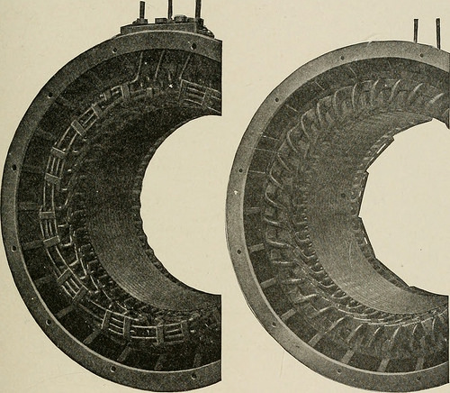
Image by Web Archive Book Pictures
Identifier: cyclopediaofappl04amer
Title: Cyclopedia of applied electricity : a general reference function on direct-present generators and motors, storage batteries, electrochemistry, welding, electric wiring, meters, electric lighting, electric railways, power stations, switchboards, energy transmission, alternating-present machinery, telegraphy, etc.
Year: 1916 (1910s)
Authors: American Technical Society
Subjects: Electric engineering
Publisher: Chicago : American Technical Society
Contributing Library: Northeastern University, Snell Library
Digitizing Sponsor: Northeastern University, Snell Library
View Book Page: Book Viewer
About This Book: Catalog Entry
View All Pictures: All Images From Book
Click right here to view book on-line to see this illustration in context in a browseable on-line version of this book.
Text Appearing Prior to Image:
ALTERNATING-Existing MACHINERY 175 Curtis Turbo-Alternator. A general view of a Curtis steam tur-bine alternator, constructed by the Common Electric Firm, is shownin Fig. 183. This unit is rated at 5,000 kilowatts, 13,000 volts,25 cycles, and 750 revolutions per minute. As is usual with Curtisturbo-alternators of big size, this is of the vertical type. Thegenerator is positioned at the leading of the unit and the turbine wheels
Text Appearing Soon after Image:
Fig. 184. Two Views of Stationary Armature of Curtis Alternator are below. The stationary armature with the clamping devices forrigidly supporting the coils is shown in Fig. 184. Fig. 185 is a view of a smooth core rotor for a 9,000-kilowattvertical variety of Curtis turbo-alternator. A function of interest isthe strategy employed for the attachment of the shields for the endwindings. The outer retaining cylinders are secured to the innershell by a huge quantity of short bolts which eliminate a portion of thestress of the end windings from the outer shell. The rotor is so 187 176 ALTERNATING-Existing MACHINERY designed that it acts as a powerful fan, forcing air throughout theparts of the generator requiring ventilation. The positive aspects claimed for the vertical shaft sort of Curtisturbine for large machines are: (1) The relative positions of revolving and stationary parts are definitelyfixed by the step-bearing. (two) The stationary portion is symmetrical, and cost-free from distortion by heat. (three) The shaft
Note About Photos
Please note that these pictures are extracted from scanned web page pictures that might have been digitally enhanced for readability – coloration and look of these illustrations may not perfectly resemble the original function.