A couple of good turbine blade machining pictures I located:
Image from page 317 of “Stationary steam engines, straightforward and compound specially as adapted to light and energy plants” (1902)
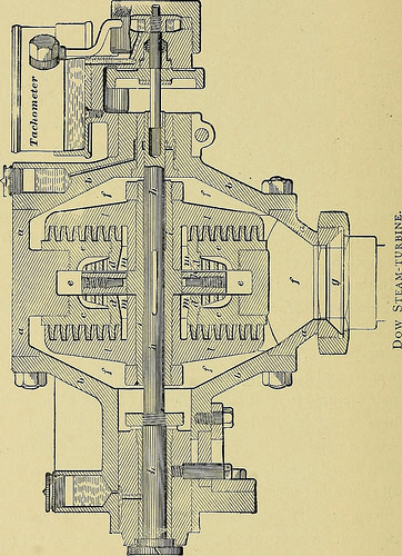
Image by Internet Archive Book Images
Identifier: stationarysteame03thur
Title: Stationary steam engines, simple and compound especially as adapted to light and energy plants
Year: 1902 (1900s)
Authors: Thurston, Robert H[enry], 1839-1903. [from old catalog]
Subjects: Steam-engines
Publisher: New York, J. Wiley & sons London, Chapman & Hall, limited
Contributing Library: The Library of Congress
Digitizing Sponsor: The Library of Congress
View Book Page: Book Viewer
About This Book: Catalog Entry
View All Photos: All Images From Book
Click right here to view book on-line to see this illustration in context in a browseable online version of this book.
Text Appearing Prior to Image:
unds and 1 cubic foot. In this turbine the steam enters by means of the passage eeand finds exit by means of/// to the exhaust-pipe g (web page 280). The primary shaft,/z/z, is carried on journals at each and every side thecasing, as observed, and a sleeve, //, stiffens the central element ofthe shaft and carries the turbine-wheels appropriate, //, of whicha pair are employed to insure a longitudinal balance of pressures.These are inward-flow turbines, compounded byhaving a quantity of concentric circles of blades working inseries, in conjunction with the guide-blades, on cc, as iswell shown in the subsequent figure. Steam entering from ee should pass through the balance-disk, k, on the shaft, the spaces on either side and the pas-sages tnm to reach the turbine-disk. This keeps the sleeveand the three disks automatically adjusted longitudinallyat the intended quite minute distance from the guide-disks. STEAM ENGINES FOR and insures that contact shall not take spot. The sleeveis splined to the shaft, and permits slight endwise motion
Text Appearing Following Image:
of the latter without having affecting the action of the turbine.The latest development of the steam-turbine in modern day ELECTRIC LIGHTING PLANTS. 281 function is a modification of the machine of Branca of 1629,of which an illustration is given, web page 282, as drawn by the
Note About Photos
Please note that these pictures are extracted from scanned page photos that could have been digitally enhanced for readability – coloration and appearance of these illustrations might not completely resemble the original function.
Image from page 319 of “Modern mechanism, exhibiting the most current progress in machines, motors, and the transmission of power, becoming a supplementary volume to Appletons’ cyclopaedia of applied mechanics” (1892)
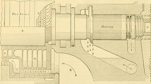
Image by Internet Archive Book Photos
Identifier: modernmechanisme00benj
Title: Modern day mechanism, exhibiting the newest progress in machines, motors, and the transmission of power, being a supplementary volume to Appletons’ cyclopaedia of applied mechanics
Year: 1892 (1890s)
Authors: Benjamin, Park, 1849-1922
Subjects: Mechanical engineering
Publisher: New York, D. Appleton
Contributing Library: Mugar Memorial Library, Boston University
Digitizing Sponsor: Boston University
View Book Web page: Book Viewer
About This Book: Catalog Entry
View All Pictures: All Images From Book
Click right here to view book on the internet to see this illustration in context in a browseable on the internet version of this book.
Text Appearing Just before Image:
Fig. 11.—Compound steam turbine. and by successive measures the turbines are improved in size or location of passage-way, so as toaccommodate the boost of volume, and to sustain a suitable distribution of stress and
Text Appearing Following Image:
Kio. 12.—Compound steam turbine. ENGINES, STEAM EOTARY. 299 velocity all through the entire series of turbines. The areas of the successive turbines are soarranged that the velocity of the flow of steam shall bear all through the series about thesame ratio to the speed of the blades and as far as feasible this ratio of velocity is so fixedas to give every single turbine of the series its maximum efficiency. The two equal series of turbineson every single side of the central steam-inlet / balance each other as regards any end stress onthe spindle of the motor, and as a result take away any tendency to undue put on on the collars of thebearings B. The turbines aie constructed of alternate revolving and stationary rings ofblades. The revolving blades r. Fig. 12, are cut with correct or left hand obliquity on the out-side of a series of brass rings, which are threaded upon the hoiizontal steel driving-spindle s,and secured upon it by feathers the finish rings form nuts, which are screwed upon the spindleand hold th
Note About Photos
Please note that these images are extracted from scanned page pictures that could have been digitally enhanced for readability – coloration and appearance of these illustrations may possibly not perfectly resemble the original work.