")
A few good all axis machining pictures I discovered:
Image from web page 145 of “Machine style” (1906)
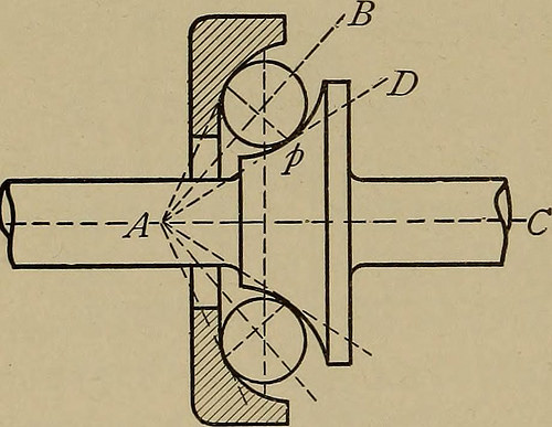
Image by Net Archive Book Images
Identifier: machinedesign02benj
Title: Machine design
Year: 1906 (1900s)
Authors: Benjamin, Charles H[enry], 1856- [from old catalog]
Subjects: Machine design
Publisher: New York, H. Holt and firm
Contributing Library: The Library of Congress
Digitizing Sponsor: The Library of Congress
View Book Page: Book Viewer
About This Book: Catalog Entry
View All Pictures: All Images From Book
Click here to view book on the internet to see this illustration in context in a browseable on the internet version of this book.
Text Appearing Before Image:
t the bearing just shown to four pointcontact, it would only be essential to change the onecone into two cones tangent to the ball at c and d. To reduce it to two point contact the points a and bare brought together to a point opposite p. As in thislast case the ball would not be confined to a definitepath it is customary to make a single or each surfaces con-cave conoids with a radius about three fourths thediameter of the ball. See Fig. 52. 59. Step-Bearings. Thesame principles apply asin the preceding articleand the axis and pointsof speak to could be variedin the identical way. Themost typical kind ofstep-bearing consists oftwo flat circular platesFig. 52. separated by one particular or far more rings of balls. Each and every ring have to be kept in spot byone or much more loose retaining collars, and these in turnare the result in of some sliding friction. This is a bear-ing with two point contact and the balls turning onhorizontal axes. If the space in between the plates isfilled with loose balls, as is often carried out, the rubbing
Text Appearing Following Image:
STEP-BEARINGS. 121 of the balls against every other will trigger considerablefriction. To guide the balls with no rubbing friction threepoint get in touch with is typically used. Fig. 53 illustrates a bearing of this character. The a b ■> k- 1 p i B d(r A n Wmm, ID mi Fig. 53. approach of style is shown in the figure, the principlebeing the exact same as in Fig. 51. By comparing the letter-ing of the two figures the similarity will be readily seen. This last bearing perhaps converted to 4 pointcontact by producing the uppercollar of the identical shape asthe reduced. To guide theballs in two point contactuse is often created ofa cage ring, a flat collardrilled with holes just atrifle larger than the ballsand disposing them eitherin spirals or in irregular Fig. 54. order. See Fig. 54. This approach has
Note About Pictures
Please note that these pictures are extracted from scanned page pictures that may possibly have been digitally enhanced for readability – coloration and look of these illustrations may possibly not completely resemble the original work.
Image from web page 140 of “Machine design” (1906)
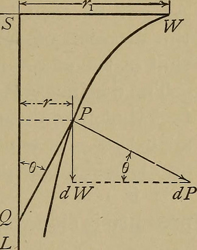
Image by Net Archive Book Pictures
Identifier: machinedesign02benj
Title: Machine design
Year: 1906 (1900s)
Authors: Benjamin, Charles H[enry], 1856- [from old catalog]
Subjects: Machine design and style
Publisher: New York, H. Holt and firm
Contributing Library: The Library of Congress
Digitizing Sponsor: The Library of Congress
View Book Page: Book Viewer
About This Book: Catalog Entry
View All Pictures: All Images From Book
Click here to view book on the web to see this illustration in context in a browseable on the web version of this book.
Text Appearing Before Image:
rs unevenly, normally as-suming a concave shape as noticed in profile. 55. Schieles Pivot. By experimenting with apivot and bearing made of some friable material, it wasshown that the outline tended to turn into curved asshown in Fig. 49. This led to a mathematical investi-gation which showed that the curve would be a trac-trix under specific circumstances. This curve may be traced me-,5 C^ chanically as shown in Fig. 48. W Let the weight W be cost-free to move on a plane. Let the stringSW be kept taut and the finish Smoved along the straight line SL.Then will a pencil attached to the TO AO center of W trace on the plane a Fig. 48 . r tractrix whose axis is SL, SCHIELES PIVOT. 115 In Fig. 49 let SW=lengthof string =r and let P be anypoint in the curve. Then it isevident that the tangent PQ tothe curve is a continuous and =? Also Let a pivot be generated byrevolving the curve around itsaxis SL. As in the case of theconical pivot it can be provedthat the typical stress onan element of convex surface is
Text Appearing Following Image:
Fig. 49. dP = SWrdr (a) (dl—d$)sind Let the typical wear of the pivot be assumed to beproportional to this regular stress and to the velocityof the rubbing surfaces, i. e. standard put on proportionalto pr, then is the vertical wear proportional to prsinB But is a continual, as a result the vertical sind put on will be the very same at all points. This is thecharacteristic function and advantage of this type ofpivot. As shown in equation (a)SW^dr Cli — CL% dP rjrp SWfr.rdr di d and T _%Wfr1 r-r Wfdx1 ~ dl-dl two ~~ two .(72) T is as a result shown to be independent of d, or of the*length of pivot used, 116 MACHINE Style. This pivot is occasionally wrongly referred to as antifriction.As will be noticed by comparing equations (68) and (72)the moment of friction is fifty per cent, greater thanthat of the typical flat pivot. The distinct benefit of the Schiele pivot is in thefact that it maintains its shape as it wears and is self-adjusting. It is an costly bearing to manufactureand is seldom employed on that account. I
Note About Images
Please note that these pictures are extracted from scanned page images that might have been digitally enhanced for readability – coloration and appearance of these illustrations may not perfectly resemble the original work.