")
Some cool impeller machining pictures:
Image from page 341 of “Bulletin” (1905)
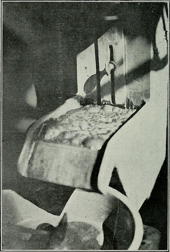
Image by Web Archive Book Pictures
Identifier: bulletin78cali
Title: Bulletin
Year: 1905 (1900s)
Authors: California. Division of Mines and Geology California. State Mining Bureau. Bulletin
Subjects: Mines and mineral sources Geology
Publisher: San Francisco [and so forth.]
Contributing Library: Gerstein – University of Toronto
Digitizing Sponsor: University of Toronto
View Book Web page: Book Viewer
About This Book: Catalog Entry
View All Pictures: All Pictures From Book
Click here to view book on the internet to see this illustration in context in a browseable on-line version of this book.
Text Appearing Before Image:
ning in the bottom of the agitation compart-ment. Both tailings and concentrates samples have been dried andweighed. At the end of all tests, each with the Hyde and the Case apparatus,the inside of the machine was thoroughly washed out to avoid contam-ination of the oils utilised. The Case (Hoover sort) Flotation :rachine (see Photo No. 72) isa laboratory unit constructed by the Denver Fire Clay Business, Denver, 302 CAI.1FOKX1A STATE iAJIXINC BIREAT. Colo. It consists of a sinjile aluminum casting comprising the agita-tion cell and a spitzkasten for the collection of the froth. Within theagitation cell are hung the shaft and impeller, the four blades of whichare set at 90°. The steel shaft is coated with lead and the impellerl)lades are created of an alloy to resist the corrosive action of acids. Apiece of heavy rul)bei tubing connects the spitzkasten and agitationcell at the ])f)ttom. About half way down from the prime of the spitz-kasten. an o|)(ning (^ inch liigh x 1 inch wide) in the wall also con-
Text Appearing Right after Image:
Photo No. 73. Froth on a Flotation Test with the Case Machine. nects witli the agitation compartment. Tliis opening is controlled bya vertical, slotted plate, with a baffle at its reduced finish. When themachine is in operation the pui]) and froth operate from the agitationcompartment, by means of this opening to the s|)itzkasten from whicli thegangue on settling to the bottom is drawn via the rubber tube bythe suction of the impellei- blades back into the agitation compartment.This gives a continuous circulation of the pulj) tlirougli the two cellsas extended as the test lasts. The ini|)ellti- shaft is driven by a G. E. QlJCKSll.VKK KESOCKCKS. 303 iiuliiftiuii iiiot(»r, tyi)e DSS, W33, 220 volts, i li. p. (iO cycles, uperatingtit 1800 i. p. 111. The larger- two of the pulleys give the impellerspeeds of 1800 and 1300 r. p. in., respectively. A lip on the edge ofthe spitzkasten supplies for the overflow of the fi-oth (see Photo Xo.73). which might also be skimmed off from time to time with the smal
Note About Images
Please note that these photos are extracted from scanned page photos that may have been digitally enhanced for readability – coloration and appearance of these illustrations may not completely resemble the original function.
Image from page 192 of “Transactions of the Institution of Mining Engineers” (1898)
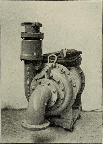
Image by Internet Archive Book Photos
Identifier: transactionsofin6162inst
Title: Transactions of the Institution of Mining Engineers
Year: 1898 (1890s)
Authors: Institution of Mining Engineers (Excellent Britain)
Subjects: Mineral industries
Publisher: Newcastle-upon-Tyne : The Institution
Contributing Library: University of Illinois Urbana-Champaign
Digitizing Sponsor: University of Illinois Urbana-Champaign
View Book Web page: Book Viewer
About This Book: Catalog Entry
View All Images: All Pictures From Book
Click here to view book on-line to see this illustration in context in a browseable on the web version of this book.
Text Appearing Prior to Image:
d finish rings the core is compressed by these members rightup to the periphery of the core-plates, thereby preventing the spreadingof the plates, which would open up pockets for corrosion. (6) If the barspassed the edges of the core with a gap, ahead of linking with the short-circuit-rings, according to usual practice for an air-machine, the waterlosses which are inevitable would be significantly elevated. (c) A veryrobust construction is obtained and the exposed surfaces are lowered toa minimum. The bars are made of drawn copper, and are enamelled exactly where theypass by means of the core. Each end of a bar is drilled in the centre fora distance equal to the axial length of the end ring steel pins are driveninto the holes, thereby swelling the finish of the bars and generating positivecontact with the end rings. Just before assembly, the ends of the bars andthe holes in the rings are tinned, and right after assembly the entire of thejoints are sweated up. There is no danger of heating on account of the water coeling, so
Text Appearing Following Image:
Fig. six. Portable Submersible MOTOR-PrMP. 172 TRANSACTIONS INSTITUTION OF MINING ENGINEERS. [VOL. LXI. that there is no trouble from sweated joints. For bigger units, even so,the bars are welded to the rings. The impeller is of the single-inlet type, cast in 1 piece, with bladeshaving the form of involutes at entrance and exit. The w^hole of the component paits for this motor-pump are shown inFig. 7. The motor-stator (1) is a totally-enclosed cast-iron frame, andthe core is assembled beneath pressure with stiff-ribbed finish-plates whichcompletely cover every single end of the core. The winding takes the standardform for three-phase, single-layer, star-connected variety, with a two-planeoverhang. The conductors are of circular cable, constructed up of a huge quantity offinely-stranded and tinned-copper wires, insulated with a specialpreparation of indiarubber. The lays of the strands are so arranged asto give a minimum diameter for a provided cross-sectional location, and to make attainable an easy and safe bend on
Note About Photos
Please note that these photos are extracted from scanned page pictures that may have been digitally enhanced for readability – coloration and look of these illustrations could not completely resemble the original function.
Image from page 582 of “The steam engine and turbine a text-book for engineering colleges” (1911)
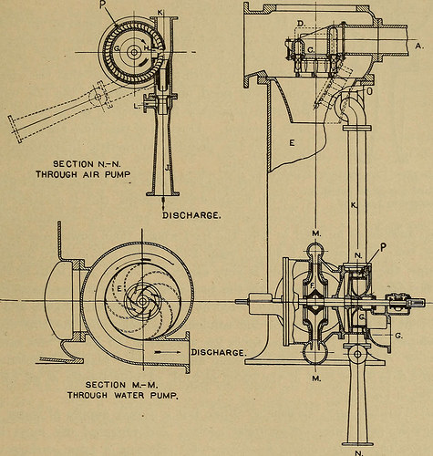
Image by World wide web Archive Book Images
Identifier: steamengineturbi01heck
Title: The steam engine and turbine a text-book for engineering colleges
Year: 1911 (1910s)
Authors: Heck, Robert Culbertson Hays, 1870-
Subjects: Steam-engines Steam-turbines
Publisher: New York, D. Van Nostrand company
Contributing Library: The Library of Congress
Digitizing Sponsor: The Library of Congress
View Book Web page: Book Viewer
About This Book: Catalog Entry
View All Photos: All Images From Book
Click here to view book on the web to see this illustration in context in a browseable on the web version of this book.
Text Appearing Just before Image:
s every single dead center and kept open for a shorttime. Then the higher-stress clearance content material at a single finish passes intothe other finish, exactly where stress is low since compression has justbegun. With this arrangement, the volumetric efficiency may possibly rise ashigh as 95 per cent. (o) Water Ejectors. — In Fig. 400, the point of specific interest isthe air pump. As to the condenser in basic, water enters at A and issprayed downward from an annular distributor C. The complete prod-uct of mixing and condensation, in a stream filling the massive funnel ornozzle, sweeps into space E, exactly where the air separates and is drawn offthrough pipe K. A plain centrifugal pump takes water from the con- § 53 (o)] CONDENSERS AND AIR PUMPS. 567 denser and on the exact same shaft with it is the impeller of turbine pump P,which sends a stream of cool water into the ejector nozzle. The streamis delivered in layers, or broken into spray, and the interstices amongdrops being necessarily filled with their surrounding atmosphere, this
Text Appearing Soon after Image:
SECTION M.-M.Through WATER PUMP, Fig. 400. — The Leblanc Condenser and Pumps. From Bulletin of Westinghouse Machine Organization. air from the condenser is carried out by and with the water. Partlyby suction of the vacuum, partly by the impeller, the current is givensufficient velocity to expel it against outside pressure. If the coldwater tank is not higher enough for flow to the pump by gravity, steamis let in at L when beginning up. This air pump can equally properly be usedwith a surface condenser. A fundamentally equivalent device, although really distinct inform, is shown in Fig. 401. Water, from a particular centrifugal pump, 568 SUNDRY STEAM APPLIANCES. [Chap. XI.
Note About Pictures
Please note that these pictures are extracted from scanned web page pictures that may possibly have been digitally enhanced for readability – coloration and appearance of these illustrations may not completely resemble the original operate.