")
A couple of nice machining turbine blades images I found:
Image from page 373 of “Twentieth century hand-book for steam engineers and electricians, with queries and answers ..” (1905)
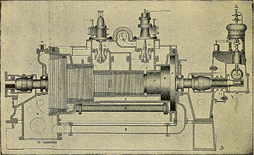
Image by World wide web Archive Book Photos
Identifier: twentiethcentury03swin
Title: Twentieth century hand-book for steam engineers and electricians, with questions and answers ..
Year: 1905 (1900s)
Authors: Swingle, C. F. [from old catalog] Horstmann, Henry Charles, 1858- [from old catalog] Tousley, Victor Hugo, 1875- [from old catalog]
Subjects: Steam engineering Electrical engineering Steam turbines
Publisher: Chicago, F. J. Drake & co.
Contributing Library: The Library of Congress
Digitizing Sponsor: The Library of Congress
View Book Page: Book Viewer
About This Book: Catalog Entry
View All Pictures: All Photos From Book
Click here to view book on the internet to see this illustration in context in a browseable on-line version of this book.
Text Appearing Before Image:
figure 130. the third and final group of blades. This arrange-ment might be likened in some measure to the triplecompound reciprocating engine. By reference to Fig. 130 it will be noticed thatt theinside of the cylinder is studded with rows of smallstationary blades and that the rotor or revolving partof the machine is also fitted with rows of little blades,comparable in shape and dimensions to the stationary 362 ENGINEERING blades. When the upper half of the cylinder is inposition, each row of stationary blades fits in betweentwo corresponding rows of moving blades. Thisarrangement might perhaps be better understood byreference to Fig. 132, which illustrates the relation ofthe stationary blades to the moving blades when inposition, and also shows by the arrows the course ofthe steam and its adjust of path brought on by thestationary blades. For the purpose of explanation the moving blades or
Text Appearing After Image:
FIGURE 131. vanes may be regarded as small curved paddles pro-jecting from the surface of the rotor, and there is alarge quantity of them, as, for instance, taking a 400K. W. machine, there are 16,095 moving blades and14,978 stationary blades, a total of 31,073. The stationary vanes, as previously explained, projectfrom the inside surface of the cylinder. Each station-ary and moving vanes are similar in shape, and aremade of tough drawn material, and they are set into THE WESTINGHOUSE-PARSONS STEAM TURBINE 363 their places and secured by a caulking process. Theblades differ in size from ^ to 7 in. in length, accord-ing to exactly where they are utilised. Referring to Fig. 130, itwill be observed that the shortest blades are placed atwhat may possibly be termed the steam end of every single section ordrum of the rotor and cylinder, and that their lengthgradually increases, corresponding with the increasedvolume of steam, till a mechanical limit is reached,when a new group of blades begins on a succeedingdrum of la
Note About Pictures
Please note that these images are extracted from scanned web page images that could have been digitally enhanced for readability – coloration and appearance of these illustrations could not perfectly resemble the original perform.
wind turbines
Image by Lori Greig