")
Check out these machining turbine rotors images:
Image from page 1244 of “Electric railway journal” (1908)
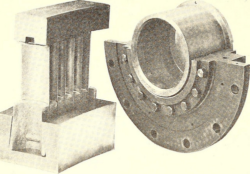
Image by Internet Archive Book Images
Identifier: electricrailway381911newy
Title: Electric railway journal
Year: 1908 (1900s)
Authors:
Subjects: Electric railroads
Publisher: [New York] McGraw Hill Pub. Co
Contributing Library: Smithsonian Libraries
Digitizing Sponsor: Smithsonian Libraries
View Book Page: Book Viewer
About This Book: Catalog Entry
View All Images: All Images From Book
Click here to view book online to see this illustration in context in a browseable online version of this book.
Text Appearing Before Image:
Fig. 2—Turbo-Generator Set of 10,000-hp Capacity 10,000-hp turbo-generator. Fig. 3 shows the constructionand the connection of the various regulating organs of theturbine, wherein the parts seen from the front of the tur-bine are cut in a vertical plane. The letters in Figs. 1 and3 refer to the table on page 1171. turbine casing. The nozzle segments are machine-cut outof solid metal. The shaft or rotor B (Fig. 1) consists of a hollow steeldrum, machined inside and out, with solid, polished shaft-ends joined to the rotor by flanges. 1170 ELECTRIC RAILWAY JOURNAL. [Vol. XXXVIII, No. 23. The fastening of the blades (Fig. 4) is done withoutriveting or calking and therefore does not call for skilledworkmen. A ridge on the concave side of the drop-forgeddistance block corresponding to a notch in the back of theblade firmly secures the latter. The high-temperature
Text Appearing After Image:
pie collar thrust bearing and in the larger sizes by an oil-balancing disk C (Fig. 1). The oil is delivered by a spe-cial pump into the space between the thrust-balancing diskand the thrust-block. Thence it escapes through the annu-lar slot at the periphery of the disk, which is narrowed inproportion as the axial thrust increases, thus auto-matically regulating the oil pressure. THE OIL-PRESSURE SYSTEM The most characteristic feature of the turbine isthe oil-pressure system (Fig. 3). Oil is used notonly for the lubrication of the bearings, but part ofit serves to operate all the controlling and safetymechanism of the turbine, namely, governor N, servo-motor P, speed-changing device W, overload valvesH… H3, emergency governor R, thrust-balancing disk,
Note About Images
Please note that these images are extracted from scanned page images that may have been digitally enhanced for readability – coloration and appearance of these illustrations may not perfectly resemble the original work.
Helicopter Eurocopter bottom view
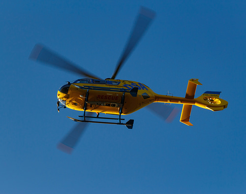
Image by roman.kopacek
Photographs taken with an example of the work of rescuers August 29, 2015 in Jablonec nad Nisou, Czech Republic
Eurocopter EC135T2
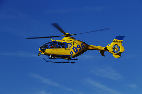
Image by roman.kopacek
Photographs taken with an example of the work of rescuers August 29, 2015 in Jablonec nad Nisou, Czech Republic