")
A few nice machining turbine rotors pictures I discovered:
Image from web page 302 of “Pacific service magazine” (1912)
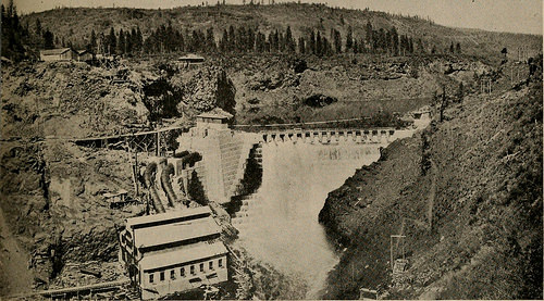
Image by Web Archive Book Images
Identifier: pacificservicema1019paci
Title: Pacific service magazine
Year: 1912 (1910s)
Authors: Pacific Gas and Electric Business
Subjects: Pacific Gas and Electric Organization Electric utilities Electrical engineering Public utilities
Publisher: San Francisco : Pacific Gas and Electric Organization
Contributing Library: San Francisco Public Library
Digitizing Sponsor: San Francisco Public Library
View Book Page: Book Viewer
About This Book: Catalog Entry
View All Photos: All Images From Book
Click here to view book on the internet to see this illustration in context in a browseable on-line version of this book.
Text Appearing Prior to Image:
ge. Up to this time the SiskiyouDistrict had been dependent upon thetransmission program more than the divide fromMedford for energy in the course of the peak load.The installation of the very first turbine atCopco brings the generator capacity abovethe peak load demand, so that the trans-mission line more than the variety is now usedfor standby service. This network oflines is exclusive in that it is supplied en-tirely by hydro-electric installations, nosteam plants being in any way connectedwith it. Each branch of the technique hasa little plant of its personal close to the centerof distribution, which is augmented bypower from the huge central plants. Situated just two miles from the FallCreek plant, constructed in 1903 and the first ofthe numerous now operating in parallel,Copco presents many contrasts with itspredecessor, as shown by the followingtable: CapacityPlant Power Source H. P. UltimateHead in Ft. Copco, AUis-Chalmers Turbine. .18,600Fall Creek, Pelton Water Wheel. 1,000 . 500. 1,250 125730730730 Pacific Service Magazine 255
Text Appearing Following Image:
ydro-Electric Energy Plant atlounty, California The turbine is of the low head variety,rated at 18,600 h. p. The double wheel issupplied by two ten-foot penstocks, anddischarges by way of a center outlet be-tween the wheels. The comparativelyslow speed of 200 r. p, m. necessitated animmense machine for the 12,000-kva. gen-erator, the rotor alone weighing 85,000pounds. A fair notion of the size of thisapparatus can be obtained when it isknown that to transport these heavypieces down the almost perpendicularwalls of the canyon necessitated thebuilding of a zigzag railroad with a max-imum grade of ten per cent. Two 200-k. w. exciters are operated by modest indi-vidual turbines. Generation of energy isat 2300 volts, two banks of transformersstepping up to 34,000 Delta and 60,000 Yfor transmission. Sooner or later it is plannedto make all the lines 60 kv. The energy residence is located at the footof the dam, the penstocks leading directlyfrom the leading of the dam to the turbine. Copco, on Klamath The height of
Note About Photos
Please note that these pictures are extracted from scanned web page pictures that might have been digitally enhanced for readability – coloration and look of these illustrations may possibly not completely resemble the original operate.
Image from web page 162 of “American hydroelectric practice a compilation of beneficial data and data on the design and style, building and operation of hydroelectric systems, from the penstocks to distribution lines” (1917)
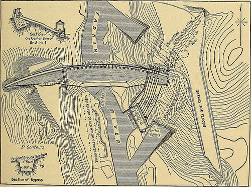
Image by World wide web Archive Book Photos
Identifier: americanhydroele00tayl
Title: American hydroelectric practice a compilation of useful data and info on the style, construction and operation of hydroelectric systems, from the penstocks to distribution lines
Year: 1917 (1910s)
Authors: Taylor, William T. (William Thomas), b. 1877 Braymer, Daniel Harvey, 1883-1932
Subjects: Hydroelectric power plants
Publisher: New York, McGraw-Hill Book Company, inc.
Contributing Library: Northeastern University, Snell Library
Digitizing Sponsor: Boston Library Consortium Member Libraries
View Book Page: Book Viewer
About This Book: Catalog Entry
View All Photos: All Images From Book
Click here to view book on the web to see this illustration in context in a browseable on the internet version of this book.
Text Appearing Prior to Image:
terest in mechanical design and style, notably the use of steel-plate scrollcasings embedded in concrete and a scheme of dismantling the runner frombelow as shown in the accompanying illustration. The runner diameter is108 in., the speed 154 r. p. m. and the head 165 to 180 ft. The casing inlet LOW, MEDIUM AND Higher HEAD DEVELOPMENTS 141 is 12 ft. in diameter and a tapering thimble connects to the 15 ft. penstock.The upper portion of the draft tube is of cast iron and telescopes into the sec-tion below, which is molded in the concrete substructure. The draft tubeis 7 ft. in diameter at the prime but right away begins to flare, flattening asit tends to make the usual appropriate angle turn with the outlet 32 ft. wide by 13 ft. three in.high. Ratings of Turbines and Generators.—As the head offered for theoperation of these units will vary considerably two guarantees of outputsat provided heads have been produced. Each and every unit is made to provide to the gen-erator shaft not significantly less than 27,000 hp. when operating beneath an successful
Text Appearing Following Image:
Fig. 81.—Locations of Old and New Energy Homes, Tunnels and Wells of the Earlierand Final Designs for Yadkin River Improvement head of 165 ft. and a speed of 154 r. p. m. Under these situations it willdevelop an efficiency of not significantly less than 90.5 per cent., efficiency getting definedas ratio of water horsepower delivered to the unit to mechanical horsepoweroutput at the turbine shaft. Every single unit also is assured to deliver notless than 31,000 hp. operating beneath an efficient head of 180 ft. and at 154r. p. m. Tests on a 32-in model runner conducted at Holyoke, Mass.,showed an efficiency of virtually 91 per cent. The generators for these units are 28 pole, 13,200 volt machines rated at18,000 kva. They have, even so, an overload assure of 22,500 kw.at unity energy element. The efficiency at 18,000 kw. and unity energy 142 HYDROELECTRIC PRACTICE factor is 96.9 per cent. The stator is 19 ft. 6 in. in diameter and the rotor14 ft. 9 in. The rotor flywheel effect (WR^) is roughly 4,00
Note About Pictures
Please note that these pictures are extracted from scanned page images that may have been digitally enhanced for readability – coloration and look of these illustrations may not completely resemble the original function.
Turbines and Towers
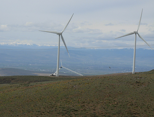
Image by brewbooks
Turbines and Towers
127 wind turbine generators, spanning across 9,000 acres near Ellensburg, Washington.
Towers are 221 ft higher at hub, 13.2 ft wide base and 7.6 ft wide at leading and weigh 104 tons. Each and every turbine consists of 3-blades, 129 ft lengthy, 11.62 ft at widest and 1.6 ft at tip with every single blade weighing 14,300 lbs. The rotor (blades, hub and nose cone) weighs 42 tons.
Turbine generators are V80-1.8 MW machines manufactured by Vestas, a Danish company. Each and every generator can generate 690 volts, which is stepped-up to 34,500 volts by an on-board transformer. The generator is housed inside a fiberglass nacelle.
The generator and nacelle collectively weigh 69 tons.
Total height with a blade fully extended is 351 ft and total weight is around 270 tons. These are the biggest wind turbine generators in Washington State (as of 2007)
Each and every tower foundation reaches a minimum depth of 25 ft and a maximum of 32 ft depending on bedrock depth and requires an typical of one hundred to 260 cubic yards of concrete. Every foundation requires 120 anchor bolts that span from the surface of the ground to the bottom of the foundation. A single 28 ft anchor bolt weighs around 150 lbs.
Rotors turn 15.five rpm, turning clockwise (front view) with a rotor diameter of 264 ft, larger than a wingspan of a Boeing 747.
Turbines can make electrical energy at wind speeds as low as 9 mph, reaching their peak of production at 31 mph and shut down at continual wind speeds of 56 mph. The prevailing winds are from the northwest.
Every single turbine is capable of making 1.eight megawatts, or a total of 229 megawatts of capacity, enough electricity to serve around 73,000 properties when all 127 are producing at full capacity.
i042907 355