
Check out these 4 axis milling images:
Image from page 47 of “Tests on plain and reinforced concrete beams” (1904)
Image by Internet Archive Book Images
Identifier: testsonplainrein00blac
Title: Tests on plain and reinforced concrete beams
Year: 1904 (1900s)
Authors: Blackburn, Roy Jabez Brown, Seymour Dewey Engstrom, Roy Victor Mills, Floyd Earl
Subjects: Concrete beams Theses Theses
Publisher:
Contributing Library: University of Illinois Urbana-Champaign
Digitizing Sponsor: University of Illinois Urbana-Champaign
View Book Page: Book Viewer
About This Book: Catalog Entry
View All Images: All Images From Book
Click here to view book online to see this illustration in context in a browseable online version of this book.
Text Appearing Before Image:
Ii 19 beams there is much less uniformity in the results thv.n with thereinforced beams. Referring to the curves for No. 11 and No. 18, it will benoticed that the neutral axis is located approxiriately 6 3/4 in-ches from the top and in all subsequent calculations the posi-tion of the neutral axis will be taken as at the center of thedepth of the beam. The modulus of rupture was determined as follows, referencebeing made to the figure below. 1 w A. I -L Since the taending moment-for the applied load at all pointsbetween the loads is the same and since the bending momentdue to the weight of the beam is greatest at trie middle, thedangerous section is evidently at the middle. This assumptionwas verified by the tests.W= toy a/ a/^/P^^^^^ /oc/a^ //? j?oc//?c^^.;i^^/^/pf /i^^a^ //7 per ///reor /7?o/77e/?/- ^/ £^c^e /a A/. /i^ – r. .. „ h<£/^/Ff ^/ <i»^a/7?. ou_L^ L X X / X /^^ -zoj r^x /^^ 4 ^ ^^
Text Appearing After Image:
20 7 ^ /^x733^ 37^ 37^ Hodulu^ oi Huplvre of Concrete. IV(?/^/pf per //. // /7/ 26> 0 0 // /7/ 3/2 25 /?/ ^3 5 5 334 24 2C> /V/. 6 S Soo 3a 355 3/ 34 / 347:.^ Tiaeoe resultgive fairly uniform values for the modulusof rupture except with No. 24. Neglecting No. 24 , the averagevalue is 350 Ih, per sq. in. The weight of the beam per linealfoot was assumed in all cases except No. 26 and No. 30, butprobahly the true value lies very close to the assumed valuesince in all cases where the beams were weighed, the weight ofthe concrete per cubic foot was about 151 lb. In general the
Note About Images
Please note that these images are extracted from scanned page images that may have been digitally enhanced for readability – coloration and appearance of these illustrations may not perfectly resemble the original work.
Image from page 43 of “Tests on plain and reinforced concrete beams” (1904)
Image by Internet Archive Book Images
Identifier: testsonplainrein00blac
Title: Tests on plain and reinforced concrete beams
Year: 1904 (1900s)
Authors: Blackburn, Roy Jabez Brown, Seymour Dewey Engstrom, Roy Victor Mills, Floyd Earl
Subjects: Concrete beams Theses Theses
Publisher:
Contributing Library: University of Illinois Urbana-Champaign
Digitizing Sponsor: University of Illinois Urbana-Champaign
View Book Page: Book Viewer
About This Book: Catalog Entry
View All Images: All Images From Book
Click here to view book online to see this illustration in context in a browseable online version of this book.
Text Appearing Before Image:
t. On pages 38 to 72 there is given a series of tablesrshowingthe original data as taken during the tests on the several beams.These t. bulated data are not designed to shov/ any results or con-clusions biit are included in this report for the use of any onewho may for any reason wish to study the original notes. At the top of each page is indicated the manner of reinforcement used, if anyj the size of the beam and the span at whichtested. In the tables are included the loading in pounds,-thedeflections in inches unless noted otherwise and the reading ofthe extensometors. There is also a columngiving such data as the location of the contact points, bow the instruments Aereattached, the maximum loading, the manner of failure wheneverpoGGihle, rnd a record of such phenomena as seemed jjertinent. The beams were tested when 60 days old. In some casesthe time over ran 3 or 4 days, lout the largest variation from60 days was 4 and in most cases the heams were tested on thedate they came due.
Text Appearing After Image:
18. DISCUSSION OF RESULTS.On plates 11 to ^5 vill be found a graphical representationof results deduced from the tests of the beams. These diagramscontain in general four curves showing; first, the contractionof the upper fibre; second, the elongation of the steel, or, inthe case of the plain concrete beams, the elongation of the low-er fibre; third, the actual deflec-tions (in blue); and fourth, theposition of the neutral axis. Thevalues plotted for the contractionand elongation of the upper andlover fibres are rctual values cal-culated graphically from the exten.-someter observations.A diagram drawn to a large scale on coordinate paper, theprinciple of which is shown by thesketch above, was used inthe determination. C is the contraction observed on extensome-ter U, and c is therefore the compression of the upper fibre.L is elongation observed on extensometer B, S being the trueelongation of steel. In the tests on plain concrete beams an effort was made todetermine, first the modulu
Note About Images
Please note that these images are extracted from scanned page images that may have been digitally enhanced for readability – coloration and appearance of these illustrations may not perfectly resemble the original work.
Image from page 262 of “The dictionary of arts, sciences and manufactures … embracing in all nearly three thousand articles on arts and sciences” (1859)
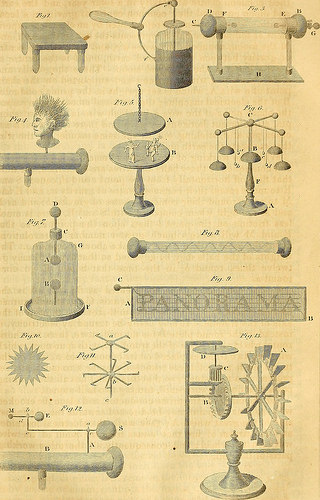
Image by Internet Archive Book Images
Identifier: dictionaryofarts02smit
Title: The dictionary of arts, sciences and manufactures … embracing in all nearly three thousand articles on arts and sciences
Year: 1859 (1850s)
Authors: Smith, James, author of the Panorama of science and art
Subjects: Technology Industrial arts
Publisher: Boston, Phillips, Sampson, and Co.
Contributing Library: Smithsonian Libraries
Digitizing Sponsor: Smithsonian Libraries
View Book Page: Book Viewer
About This Book: Catalog Entry
View All Images: All Images From Book
Click here to view book online to see this illustration in context in a browseable online version of this book.
Text Appearing Before Image:
that S and E go onceround a. 4. The electrical mill is represented at fig. 13. A is thewater-wheel, B the cog-wheel on its axis, C the trundle turnedby that wheel, and D the running mill-stone on the top of theaxis of the trundle. It may easily be turned by electricity, ifinstead of the round plate D for the mill-stone, there be a hori-zontal wheel on the axis of the trundle C, with spur-cogs, whichwill turn two trundles placed on its opposite sides ; and on thetop of each axis of these trundles, may be a round plate, re-presenting a mill-stone ; so that this model has all the workingparts of a double water-mill, turning two mill-stones. Set the mill near the prime conductor, and place the crookedwire, so that its point may be directed towards the uppermostside of the great wheel A; then work the electrical machine,and the stream of fire that issues from the point of the wirewill turn the wheel; and consequently all the other workingparts of the mill. ,!•,[, K(Ti! I C IT V /->,/
Text Appearing After Image:
(StifftYtr//./,s/, V ELECTRICITY. 231 Miscellaneous experiments. The Thunder House. The usefulness of metallic conductors applied to houses, andthe bad effects which may result from the lightning strikingupon a house not properly secured, may be shewn in a veryconvincing manner by the instrument represented atfig.l,pl.III.A is a board about three-quarters of an inch thick, and shapedlike the gable end of a house. This board is fixed perpendi-cularly upon the bottom board B, upon which the perpendicularglass pillar CD is also fitted in a hole about eight inches dis-tant from the base of the board A. A square hole ILMK, abouta quarter of an inch deep, and nearly one inch wide, is madein the board A, and is filled with a square piece of wood nearlyof the same dimensions. It is mentioned nearly of the samedimensions, because it must go so easily into the hole, that itmay drop off by the least shaking of the instrument. A wireLK is fastened diagonally to this square piece of wo
Note About Images
Please note that these images are extracted from scanned page images that may have been digitally enhanced for readability – coloration and appearance of these illustrations may not perfectly resemble the original work.