
Image from page 291 of “The flotation process” (1916)
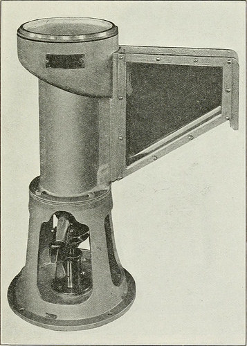
Image by Internet Archive Book Images
Identifier: flotationprocess00richuoft
Title: The flotation method
Year: 1916 (1910s)
Authors: Richard, Thomas Arthur, 1864-
Subjects: Flotation
Publisher: San Francisco Mining and Scientific Press
Contributing Library: Gerstein – University of Toronto
Digitizing Sponsor: University of Toronto
View Book Web page: Book Viewer
About This Book: Catalog Entry
View All Pictures: All Images From Book
Click right here to view book on the web to see this illustration in context in a browseable online version of this book.
Text Appearing Just before Image:
o the froth-box and down into the spitzkasten, where the froth can be removed. A discharge-plug at the bottom of the machine makes it possible for the flushingout of tailing following the test has been completed. So cautious hasbeen the style of this test-machine that even this discharge-plugis beveled to match flush with the bottom of the machine and hence affordno dead space in which the solids might settle. The spitzkasten is long and narrow, in order to permit a deepfroth to be formed and to travel more than as lengthy a space as possible,before reaching the discharge. This tends to let much more of the TESTING ORES FOR THE FLOTATION Method 283 entrained gangue to settle out of the mineral froth. The sides ofthe ■ spitzkasten are of heavy plate-glass, every single fastened to a metalframe by means of screws. The wrought-iron shaft projects througha brass stuffing-box and is supported by a ball-bearing beneath. Allthe other metal parts are of cast aluminum. The little variable-speed motor may possibly be of either D. C. or A. C.
Text Appearing Following Image:
FlG. 58. THE JA^^■EY MACHINE. COVER INVERTED. kind. F. G. Janney recommends the use of a Common Electric,shunt-wound, direct-current motor, for 230 volts, with a rated speedof 1700 r.p.m. and ^ hp. The impeller-shaft is to be driven at 1900r.p.m. maximum speed. For speed-manage he recommends a Basic 284 THE FLOTATION Process Electric direct-existing field-rheostat, with an ampere capacity of1.25 to .063 at 250 volts. In our personal laboratory it was desirable to use the ordinary city-lighting circuit of 110 volts, A. C. On that account we have found
Note About Pictures
Please note that these pictures are extracted from scanned web page images that could have been digitally enhanced for readability – coloration and appearance of these illustrations may not perfectly resemble the original function.