
Check out these turbine blade producers photos:
Steven F. Udvar-Hazy Center: Lockheed Martin X-35B Joint Strike Fighter, with other modern jet aircraft
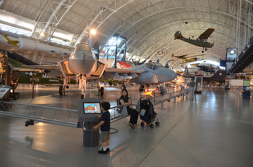
Image by Chris Devers
Quoting Smithsonian National Air and Space Museum | Lockheed Martin X-35B STOVL:
This aircraft is the initial X-35 ever built. It was originally the X-35A and was modified to include the lift-fan engine for testing of the STOVL concept. Amongst its a lot of test records, this aircraft was the initial in history to attain a quick takeoff, level supersonic dash, and vertical landing in a single flight. It is also the initial aircraft to fly employing a shaft-driven lift-fan propulsion program. The X-35B flight test system was a single of the shortest, most powerful in history, lasting from June 23, 2001 to August 6, 2001.
The lift-fan propulsion program is now displayed next to the X-35B at the Steven F. Udvar-Hazy Center close to Dulles Airport.
On July 7, 2006, the production model F-35 was officially named F-35 Lightning II by T. Michael Moseley, Chief of Employees USAF.
Transferred from the United States Air Force.
Date:
2001
Dimensions:
Wing span: 10.05 m (33 ft in)
Length: 15.47 m (50 ft 9 in)
Height: approximately 5 m (15 ft in)
Weight: around 35,000 lb.
Supplies:
Composite material aircraft skin, alternating steel and titanium spars. Single-engine, single-seat configuration includes lift-fan and steering bars for vertical flight.
Physical Description:
Quick takeoff/vertical landing variant to be employed by U.S. Air Force, U.S. Marines and the United Kingdom, equipped with a shaft-driven lift fan propulsion program which enables the aircraft to take off from a brief runway or little aircraft carrier and to land vertically.
Engine: Pratt & Whitney JSF 119-PW-611 turbofan deflects thrust downward for short takeoff/vertical landing capability. The Air Force and Navy versions use a thrust-vectoring exhaust nozzle. The Marine Corps and Royal Air Force/Navy version has a swivel-duct nozzle an engine-driven fan behind the cockpit and air-reaction manage valves in the wings to provide stability at low speeds.
Other significant subcontractors are Rolls Royce and BAE.
• • • • •
Quoting Smithsonian National Air and Space Museum | Grumman A-6E Intruder:
The Navy’s expertise in the Korean War showed the need for a new lengthy-range strike aircraft with higher subsonic overall performance at very low altitude–an aircraft that could penetrate enemy defenses and find and destroy tiny targets in any weather. The Grumman A-six Intruder was made with these demands in thoughts. The Intruder very first flew in 1960 and was delivered to the Navy in 1963 and the Marine Corps in 1964.
The Navy accepted this airplane as an "A" model in 1968. It served beneath harsh combat circumstances in the skies over Vietnam and is a veteran of the 1991 Desert Storm campaign, when it flew missions throughout the initial 72 hours of the war. It has accumulated far more than 7,500 flying hours, more than six,500 landings, 767 carrier landings, and 712 catapult launches.
Transferred from the United States Navy, Office of the Secretary
Date:
1960
Nation of Origin:
United States of America
Dimensions:
Overall: 16ft 2in. x 52ft 12in. x 54ft 9in., 26745.8lb. (4.928m x 16.154m x 16.688m, 12131.8kg)
Components:
Conventional all-metal, graphite/epoxy wing (retrofit), aluminium manage surfaces, titanium higher-strength fittings (wing-fold).
Physical Description:
Dual location (side by side), twin-engine, all-weather attack aircraft several variants.
Image from page 227 of “Steam turbines a sensible and theoretical treatise for engineers and students, which includes a discussion of the gas turbine” (1917)
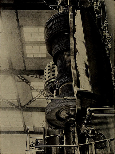
Image by Internet Archive Book Pictures
Identifier: steamturbinespra00moye
Title: Steam turbines a sensible and theoretical treatise for engineers and students, such as a discussion of the gas turbine
Year: 1917 (1910s)
Authors: Moyer, James Ambrose, 1875-
Subjects: Steam-turbines
Publisher: New York, Wiley
Contributing Library: The Library of Congress
Digitizing Sponsor: The Library of Congress
View Book Web page: Book Viewer
About This Book: Catalog Entry
View All Images: All Images From Book
Click here to view book online to see this illustration in context in a browseable online version of this book.
Text Appearing Before Image:
eases from the admission to the exhaust insuch a turbine. Because there are 58 stages, if the pressure dif-ferences were made equal for a total drop in stress of say from175 pounds per square inch to 1 pound per square inch, the dropin pressure in each and every stage would be 3 pounds per square inch.But since the steam velocity for a given distinction in pressureis really many occasions as excellent at 1 pound as at 175 pounds, such adivision is not desirable, and as an alternative the stress drop is produced tosuit blade speeds that are probably to show ideal efficiency in thevarious sections. Minimum and maximum velocities at thelow-stress finish are 500 to 700 feet per second in moderndesigns of these turbines. A large Westinghouse-Parsons turbine is shown in Fig. 101,with the upper half of the casing removed to show the rotor, * Bearing stress in pounds per square inch instances peripheral velocity of theshaft in feet per second is typically about 2500. — Proc. Inst. Elec. Engrs., June,1905. 208 THE STEAM TURBINE
Text Appearing Right after Image:
a &p Commercial Kinds 209 blades, and balance pistons. The collars on the balancepistons which form the labyrinth packing are plainly visible.The rising length of the blades of the third (exhaust)section is also really apparent. Besides the Westinghouse Machine Company of Pittsburg,Pa., other essential producers of Parsons turbines are thefollowing: Allis-Chalmers Firm, Milwaukee, Wis. C. A. Parsons & Co., Newcastle, England. Willans-Robinson Company, Rugby, England. Brown-Boveri & Co., Baden, Switzerland, and Mannheim, Germany.*British Westinghouse Company, Manchester, England. The Allis-Chalmers steam turbine is a reaction sort whichdiffers from the original Parsons machines principally in manu-facturing particulars intended to take away some of the operating diffi-culties of the older designs. An innovation in the design of theseturbines is in the arrangement and building of the balancepistons. In the older types of reaction turbines the three balancepistons have been
Note About Photos
Please note that these images are extracted from scanned page photos that could have been digitally enhanced for readability – coloration and look of these illustrations might not completely resemble the original function.
Image from web page 165 of “Steam turbines a practical and theoretical treatise for engineers and students, such as a discussion of the gas turbine” (1917)
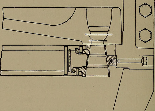
Image by Internet Archive Book Images
Identifier: steamturbinespra00moye
Title: Steam turbines a practical and theoretical treatise for engineers and students, which includes a discussion of the gas turbine
Year: 1917 (1910s)
Authors: Moyer, James Ambrose, 1875-
Subjects: Steam-turbines
Publisher: New York, Wiley
Contributing Library: The Library of Congress
Digitizing Sponsor: The Library of Congress
View Book Web page: Book Viewer
About This Book: Catalog Entry
View All Images: All Images From Book
Click right here to view book on the web to see this illustration in context in a browseable on-line version of this book.
Text Appearing Before Image:
hen blade velocity is practically half the initial velocity of thesteam. For a single wheel per stress stage. REACTION. 1. Several stages. 2. No nozzles. 3. Small drop in stress in a stage. 4. All steam velocities are low (300 to 600 feet per second). 5. Blade velocities 150 to 400 feet per second. 6. Greatest efficiency when the blade velocity is practically equal to the highest velocityof the steam. Radial Blade Clearances. In impulse turbines the radialclearance (between the blade ring and the inside of the casing)is not essential. It is one particular of the very first principles of a gooddesign of an impulse turbine that the blades shall be produced longenough to permit the steam to be discharged by means of them freelywithout choking the flow and spilling steam more than theouter edges of the blades. Since the pressure is the identical on the 146 THE STEAM TURBINE two sides of the blades, radial blade clearances in impulse tur-bines can be created of generous dimensions. (See Figs. 57 and 119, in which Curtis designs are shown.)
Text Appearing Soon after Image:
Fig. 57. Illustrates Radial and Axial Clearances in an Impulse Turbine. In reaction turbines, on the other hand, it is very necessaryto make radial clearances as little as is mechanically attainable,due to the fact in these turbines the steam expands in the moving aswell as in the stationary blades and there is a drop in pressurebetween the two sides of every row of blades. On account ofthis pressure drop there is a continuous flow of steam about theedges of the blades, which is huge or little in quantity in pro-portion to the size of the radial clearances. The clearancebetween the stationary blades fixed to the casing and the surfaceof the rotor is of course just as critical as that between themoving blades and the casing. An American manufacturer ofthe Parsons reaction turbines states that the radial clearancesare from .02 to .10 inch, varying with the diameter of the drum.These limits are given for drums in between 1 foot and 10 feet indiameter. Radial clearances of massive sizes of Parsons turbin
Note About Pictures
Please note that these photos are extracted from scanned web page images that could have been digitally enhanced for readability – coloration and appearance of these illustrations may possibly not perfectly resemble the original operate.