")
Check out these turbine blade machining images:
Image from page 271 of “Steam turbines; a practical and theoretical treatise for engineers and students, including a discussion of the gas turbine” (1917)
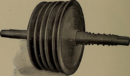
Image by Internet Archive Book Images
Identifier: steamturbinespra00moye
Title: Steam turbines; a practical and theoretical treatise for engineers and students, including a discussion of the gas turbine
Year: 1917 (1910s)
Authors: Moyer, James Ambrose, 1875-
Subjects: Steam-turbines
Publisher: New York, Wiley
Contributing Library: The Library of Congress
Digitizing Sponsor: The Library of Congress
View Book Page: Book Viewer
About This Book: Catalog Entry
View All Images: All Images From Book
Click here to view book online to see this illustration in context in a browseable online version of this book.
Text Appearing Before Image:
he first pressurestage is shown in Fig. 137. Wheel Disks. Typical Rateau disks are shown in Fig. 136.Details of construction are shown better, however, in Fig. 132.A shroud ring is fitted around the blades as illustrated in thelatter figure. The blades resemble those used in De Laval andCurtis turbines except that they have a flat projection at the rootwhich is provided to fasten them to the flange of the disk byriveting. The holes shown in the disk in Fig. 132 were drilled 252 THE STEAM TURBINE for balancing. Fig. 136 shows a group of Rateau disks assembledon the turbine shaft. Manufacturers. Rateau turbines are constructed by thepioneers, Sautter, Harle & Co., at Paris, by the MaschinenfabrikOerlikon in Switzerland and by many other companies in Europe.American types are made by the Ridgway Dynamo & EngineCompany of Ridgway, Pa., and the Southwark Foundry &Machine Company of Philadelphia. Rateau designs are fre-quently used in combination with other types, as for example
Text Appearing After Image:
Fig. 136. Ridgway Disks Assembled on the Turbine Shaft. when Curtis blading is used for the first stage and Rateau blad-ing for the remaining stages (see Fig. 137 and the example,pages 102-111). Low-Pressure Rateau Turbines are extensively used in Europeto operate with the exhaust steam from rolling mill and mineengines. Professor Rateau has designed a steam accumulator(Fig. 184) for application in such cases where the steam supplyis intermittent. It is described in Chapter IX in the discussionof low-pressure steam turbines. COMMERCIAL TYPES 253
Note About Images
Please note that these images are extracted from scanned page images that may have been digitally enhanced for readability – coloration and appearance of these illustrations may not perfectly resemble the original work.
Image from page 252 of “Steam turbines; a practical and theoretical treatise for engineers and students, including a discussion of the gas turbine” (1917)
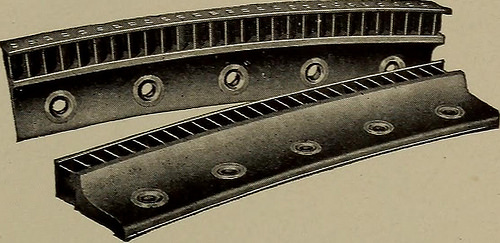
Image by Internet Archive Book Images
Identifier: steamturbinespra00moye
Title: Steam turbines; a practical and theoretical treatise for engineers and students, including a discussion of the gas turbine
Year: 1917 (1910s)
Authors: Moyer, James Ambrose, 1875-
Subjects: Steam-turbines
Publisher: New York, Wiley
Contributing Library: The Library of Congress
Digitizing Sponsor: The Library of Congress
View Book Page: Book Viewer
About This Book: Catalog Entry
View All Images: All Images From Book
Click here to view book online to see this illustration in context in a browseable online version of this book.
Text Appearing Before Image:
rtis turbines. Wheel Disks and Blades. The blade wheels are usually madeof forged steel disks similar to Fig. 216, which increase in thick- COMMERCIAL TYPES 233 ness as they approach the hub, but in larger sizes the construc-tion shown in Fig. 113 is often employed. In some very smallturbines the blades are cut in the solid rim by special machines,while others have drawn or rolled blades which are cast intosegments (Fig. 115) of bronze alloy designed to be riveted to therim. A dovetailing meth-od similar to Fig. 63 isnow generally preferredto the method of insertingthe blades by casting.The fixed blades, or inter-mediates, are also eithercut or cast in segments(Fig. 116), and are fas-tened by bolts to the interior of the casing as shown in Fig. 57.These intermediates cover only the portion of the circumferenceupon which the belt of steam delivered by the nozzles can im-pinge. To make the blades more rigid, thin bands or shroudrings are riveted in segments to projections on their ends.
Text Appearing After Image:
Fig. 115. Curtis Moving Blade Segments.
Note About Images
Please note that these images are extracted from scanned page images that may have been digitally enhanced for readability – coloration and appearance of these illustrations may not perfectly resemble the original work.