Some cool machining turbine rotors photos:
Turbines and Towers in Sagebrush Country
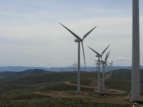
Image by brewbooks
Turbines and Towers in Sagebrush Country
127 wind turbine generators, spanning across 9,000 acres near Ellensburg, Washington.
Towers are 221 ft higher at hub, 13.2 ft wide base and 7.six ft wide at prime and weigh 104 tons. Every single turbine consists of 3-blades, 129 ft extended, 11.62 ft at widest and 1.6 ft at tip with each and every blade weighing 14,300 lbs. The rotor (blades, hub and nose cone) weighs 42 tons.
Turbine generators are V80-1.8 MW machines manufactured by Vestas, a Danish company. Every generator can generate 690 volts, which is stepped-up to 34,500 volts by an on-board transformer. The generator is housed inside a fiberglass nacelle.
The generator and nacelle together weigh 69 tons.
Total height with a blade totally extended is 351 ft and total weight is roughly 270 tons. These are the biggest wind turbine generators in Washington State (as of 2007)
Every single tower foundation reaches a minimum depth of 25 ft and a maximum of 32 ft depending on bedrock depth and takes an typical of 100 to 260 cubic yards of concrete. Every single foundation demands 120 anchor bolts that span from the surface of the ground to the bottom of the foundation. A single 28 ft anchor bolt weighs approximately 150 lbs.
Rotors turn 15.five rpm, turning clockwise (front view) with a rotor diameter of 264 ft, larger than a wingspan of a Boeing 747.
Turbines can generate electricity at wind speeds as low as 9 mph, reaching their peak of production at 31 mph and shut down at continuous wind speeds of 56 mph. The prevailing winds are from the northwest.
Each and every turbine is capable of making 1.8 megawatts, or a total of 229 megawatts of capacity, sufficient electricity to serve about 73,000 homes when all 127 are creating at complete capacity.
derived from Puget Sound Energy
www.pse.com/energyEnvironment/EnergySupply_ElectricityWin…
i042907 333
Image from page 483 of “Journal” (1882)
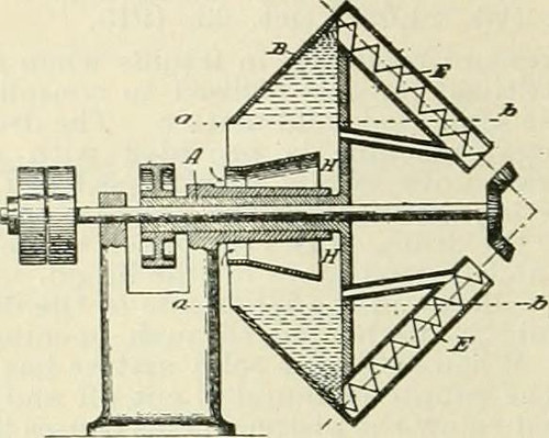
Image by Internet Archive Book Images
Identifier: journals34soci
Title: Journal
Year: 1882 (1880s)
Authors: Society of Chemical Industry (Excellent Britain) Society of Chemical Industry (Wonderful Britain). Abstracts Society of Chemical Market (Fantastic Britain). Assessment Society of Chemical Industry (Wonderful Britain). Transactions and communications
Subjects: Chemistry, Technical
Publisher: London [and so on.]
Contributing Library: Gerstein – University of Toronto
Digitizing Sponsor: University of Toronto
View Book Web page: Book Viewer
About This Book: Catalog Entry
View All Pictures: All Pictures From Book
Click here to view book online to see this illustration in context in a browseable on the internet version of this book.
Text Appearing Ahead of Image:
ing gaseous fluids hi/ means of a centrifugalfun or centrifugal comjiressor Apparatus for . Soc. dKxploitation des Appareils Hateau, Paris. Eng. P.at. i:i.9:!. .Tune 9, 1914. UnderInt. Conv..^ June 11, 191:!. The gas is passed by way of a fan and. leaving witha higher tangential velocity, passes via a whirling<l!amber into and tbroigh a turbine provided withfixed vanes and moving rotor bla<les, so arrangedthat the gas travels via the turbine in aradial path. The rotors of the turliine aremounted on a shaft, which is independent of thefan shaft. (See also Eng. Pat. 22,131 of 1901 this J., 1902. 1322.)—W. II. C. 264 Ci. L—GENERAL PLANT MACHINERY. [Har. 31, 1915. Separating solid substances from liquids Centri-fugal machine for . G. Jahn, Arnswalde, Germany. U.S. Pat. 1,124,907, Jan. 12, 1915. Date of appl., April 23, 1014. The material is fed by way of the aperture, A, into the rotating coniral drum, B, closed at 1 finish by a diaphragm, H. The separated material
Text Appearing After Image:
is discharged tlirough openings at the peripheryof the diaphiagm into the outlet conduits, E.The latter are supplied with conveyors and carrytelescopic outlet pipes, connected, by means ofrods, with a sleeve on the shaft so that theymay be moved while the drum is rotating.—W.H.C. CUtrifier for liquids Centrifugal –
Note About Photos
Please note that these photos are extracted from scanned web page images that could have been digitally enhanced for readability – coloration and look of these illustrations may possibly not completely resemble the original perform.