Some cool turbine blade machining images:
Image from web page 159 of “Official proceedings” (1901)
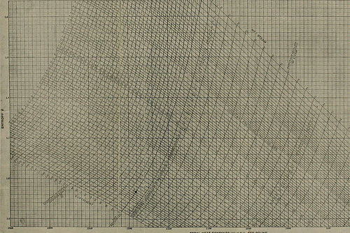
Image by Web Archive Book Pictures
Identifier: officialproceedi14rail
Title: Official proceedings
Year: 1901 (1900s)
Authors: Railway Club of Pittsburgh
Subjects: Railway Club of Pittsburgh Railroads
Publisher: Pittsburgh, Pa. : The Club
Contributing Library: Carnegie Library of Pittsburgh
Digitizing Sponsor: Lyrasis Members and Sloan Foundation
View Book Page: Book Viewer
About This Book: Catalog Entry
View All Images: All Pictures From Book
Click right here to view book on the web to see this illustration in context in a browseable online version of this book.
Text Appearing Ahead of Image:
^^^
Text Appearing Soon after Image:
K^wl- x?^ uvN .^stsx>tvxxv i^x-<:^vt TOTAL HEAT CONTENTS (H) a.T.U. PER POUND coniniercially, Imwcvcr, it is essential to supplement the tur-bine with suitable reduction gearing so that the turbine unit,consisting of turbine and gear, must be. for the sake of com-parison, taken with each other, when its positive aspects and disadvantagesare put side by side with the Curtis, Rateau or Parsons turbine. Owing to the higher stresses encountered in this type ofturbine the diameters of the wheels are reasonably small, and thematerials utilised exceptionally very good. The following table gives a very good thought of the relative pro-portions of many ditTerent De Laval machines: Horsepower 5 30 100 300 Revolutions per minute 30,000 20,000 13,000 10,000 Diameter to center of blades, inches three.94 886 19.68 29.92 Blade speed, feet per second 516 775 1,115 1,305 Owing to the high bade speed essential in the De Lavalturbine, a substantial blade fastening is essential. The bladesare made of drop forged steel and have bulb
Note About Images
Please note that these images are extracted from scanned web page images that could have been digitally enhanced for readability – coloration and look of these illustrations could not perfectly resemble the original work.
Image from page 151 of “Official proceedings” (1901)
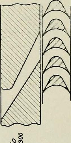
Image by Web Archive Book Images
Identifier: officialproceedi14rail
Title: Official proceedings
Year: 1901 (1900s)
Authors: Railway Club of Pittsburgh
Subjects: Railway Club of Pittsburgh Railroads
Publisher: Pittsburgh, Pa. : The Club
Contributing Library: Carnegie Library of Pittsburgh
Digitizing Sponsor: Lyrasis Members and Sloan Foundation
View Book Web page: Book Viewer
About This Book: Catalog Entry
View All Pictures: All Pictures From Book
Click here to view book on the web to see this illustration in context in a browseable on-line version of this book.
Text Appearing Prior to Image:
Text Appearing Right after Image:
f^ ^o ^f % :^: I •1200 ^^/ I K^=/^oo | W^ 74 Ill the diagrams (Figs. 5 to 11) the turbine rotors ofthe diverse sorts are taken with l)lade speeds of 500 feet persecond and an expansion of the steam from 165 pounds absokitcto I ])Ound absolute. In the diagram of the De Laval turbine (Fig. five) it willbe seen that the jet of steam has a residual or leaving velocityafter passing the wheel of 3200 feet per second, which resultsin a failure to abstract the full power of the jet proportionalto tiie square of such residual velocity. In order that 1 rowof impulse blades such as obtain in this example may possibly extractthe maximum power from the expansion of the steam fromj()^ pounds to I pound absolute, it would be needed to havea blade speed of 1730 feet per second. In tlie Ratcau machine (Fig. six) the residual velocity is2880 feet per second, representing an amount of energy un-abstracted l)y the turbine proportional to the square of thisresidual velocity. If further stages had been adde
Note About Pictures
Please note that these images are extracted from scanned web page pictures that might have been digitally enhanced for readability – coloration and look of these illustrations could not completely resemble the original function.
Image from page 702 of “The Street railway journal” (1884)
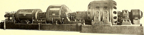
Image by Internet Archive Book Pictures
Identifier: streetrailwayjo241904newy
Title: The Street railway journal
Year: 1884 (1880s)
Authors:
Subjects: Street-railroads Electric railroads Transportation
Publisher: New York : McGraw Pub. Co.
Contributing Library: Smithsonian Libraries
Digitizing Sponsor: Smithsonian Libraries
View Book Web page: Book Viewer
About This Book: Catalog Entry
View All Photos: All Images From Book
Click here to view book online to see this illustration in context in a browseable on the web version of this book.
Text Appearing Ahead of Image:
BAND RE-SAWING MACHINE FOR RAILWAY SHOPS not vibrate, even when running on a light floor. The shafts arelarge in diameter and have bearings from 9 ins. to 14 ins. extended,operating in self-oiling boxes. The reduced wheel is a strong web andvery heavy. The upper one particular is as light as is consistent withstrength. The feed works are really potent, there getting six feed rolls,and the feed varies from 12 ft. to 120 ft. per minute, by adjustingthe expansion cones according to the function essential. The correct-
Text Appearing Following Image:
1000-KW HAMILTON-HOLZWARTH STEAM TURBINE, DIRECT CONNECTED TO 1000-KW ALTERNATOR, IN (ITERATION AT THE LOUISIANA Purchase EXPOSITION fastened to the bed-plate, and they as nicely as the shaft can slideor expand against the path in which the steam flows. The governor operates by throttling, a method which does notpresent the exact same disadvantages as in the reciprocating engine.In the latter the static pressure of the steam is reduced by athrottling valve, but in steam turbines static stress is not usedowing to the truth that all the power is converted into, kineticenergy. The regulating valve is located beneath the bed-plate, andis of the double-seated poppet-valve kind, which insures a perfectbalance. hand rolls are rigid in the boxes, but the left-hand set are elasticso as to grasp uneven stock and hold it firmly against the rigidroll, as a result making a potent Iced even on very unequal sawedlumber. All rolls are adjustable to the blade and wheels in caseof wear. With a unique self-cen
Note About Images
Please note that these photos are extracted from scanned web page images that may have been digitally enhanced for readability – coloration and appearance of these illustrations could not completely resemble the original perform.