Some cool turbine blade machining photos:
Image from page 602 of “The Americana : a universal reference library, comprising the arts and sciences, literature, history, biograhy, geography, commerce, and so forth., of the planet” (1903)
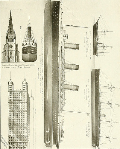
Image by Net Archive Book Pictures
Identifier: americanaunivers15beac
Title: The Americana : a universal reference library, comprising the arts and sciences, literature, history, biograhy, geography, commerce, and so on., of the planet
Year: 1903 (1900s)
Authors: Beach, Frederick Converse, 1848-1918 Rines, George Edwin, 1860- Scientific American, inc
Subjects: Encyclopedias and dictionaries
Publisher: New York : Scientific American compiling dept.
Contributing Library: University of California Libraries
Digitizing Sponsor: World wide web Archive
View Book Web page: Book Viewer
About This Book: Catalog Entry
View All Pictures: All Photos From Book
Click here to view book online to see this illustration in context in a browseable on-line version of this book.
Text Appearing Before Image:
. The tops of the revolving blades reachnearly to the outer casing of the cylinder, andthe stationary blades project inward till theyalmost scrape the revolving shaft or drum. Aseries of turbine wheels on one particular shaft arethus constituted, every a single comprehensive in itself,like a parallel-flow water-turbine but, unlikea water-turbine, the steam, soon after performingits perform in every turbine, passes on to the subsequent,preserving its longitudinal velocity withoutshock, steadily falling in stress on passingthrough each and every row of blades, and gradually ex-panding. There is no rubbing friction and nowearing parts except the bearings on which themain shaft or drum revolves. Following are the net final results of the compara-tive trials: Duchess ofHamilton King Edward Coal, I.7S8 tons, 13 cwt. 1.429 tons, 16 cwt Mileage, 15,604 12,116 Miles iier ton. 8.87 eight.47Number of days run. III 79Daily average consumption, 15 tons, 17 cwt. 18 tons, two cwt. Typical speed, i6/t knots. 185^ knots. Tt R )il N i N A < A TI ON
Text Appearing Following Image:
TURBIT — TURENNE The success of the King Edward was sopronounced that arrangements were at oncemade to construct other vessels of the sametype, to be engined also with the Parsons tur-bine! Steam-turbines of great size and powerare probably quickly to be created for marmepurposes, now that their performance has beenfound so satisfactory, and their construction ona huge scale will allow the engineer promptlyto settle several queries of interest which theearlier perform on small machines could not fullysolve. It would look that the bigger the scaleof operation the easier the difficulties of designand building and the less complicated is the approx-imate of the real to the excellent in perfecting thesystem of power conversion. Big turbinesare comparatively low in speed of revolution,and it is regarded that it would be entirelypracticable to construct an ocean steamer of largesize, driven by turbines of 30,000 or 40,000 horse-power at higher stress, or more if needed, atspeeds of revolution as low as 400
Note About Images
Please note that these photos are extracted from scanned web page images that may have been digitally enhanced for readability – coloration and look of these illustrations may not completely resemble the original work.
Image from web page 172 of “Official proceedings” (1901)
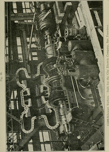
Image by Net Archive Book Pictures
Identifier: officialproceedi14rail
Title: Official proceedings
Year: 1901 (1900s)
Authors: Railway Club of Pittsburgh
Subjects: Railway Club of Pittsburgh Railroads
Publisher: Pittsburgh, Pa. : The Club
Contributing Library: Carnegie Library of Pittsburgh
Digitizing Sponsor: Lyrasis Members and Sloan Foundation
View Book Web page: Book Viewer
About This Book: Catalog Entry
View All Photos: All Pictures From Book
Click here to view book on-line to see this illustration in context in a browseable online version of this book.
Text Appearing Ahead of Image:
most economical mixture for a 30.000kw. unit is the cross-compound Westinghouse reaction turbinewith the higher-stress portion operating at 1500 revolutions andthe low-stress portion at 750 revolutions. With this arrange-ment the highest efficiency is obtained, simply because with the largevolumes of steam required to develop the higher power and theability to combine the unit into high—and low—pressure cylin-ders, operating at 1500 and 750 revolutions per minute, offers thecondition for best blading proportions all through the turbinewithout departing from standards of practice already estab-lished. This machine would be very outstanding for its highefficiencw which it is believed could not be reproduced withany other known form of turbine. The construction, even so,is significantly heavier than a single unit, an.d would be morecostly to construct and install. Economy, In order to evaluate the efficiencies which can l)e r)l)tainedwith the Curtis, Rateau. and Tarsons machines, reference is 92
Text Appearing After Image:
created to Figs. five to 11 inclusive, and-to the consideration thatthe maximum efiBcicncy for particular blade speeds in any typeof turbine is dependent on (a) design of the blade elements,(b) the relative ratio of the velocity of the blades to the velocityof the steam (c) the capacity of the turbine, and (d) the operat-ing situations. Let Sb = mean blade speed, Let Ss =: mean steam speed, Let E = blade efficiency. If steam is admitted to a wheel with a single row of impulseblades (Fig. 5), at a particular speed, Ss, and the blades are re-volved at various speeds, Sb, theoretically, the efficiency is ata maximum for a certain blade speed given by the ratio. SI) imply blade speed I Ss imply steam speed 2 S„ For an- other ratios of the efficiencv will be smaller sized. S«becoming zero when Sb = zero and when Sb = Ss- SbThe actual maximum efficiencv and the ratio ■ at which S,it is obtained rely mainly on the angles of the blades andthe frictional losses in the machine. Curve C. Fig. 19. repre-sents a
Note About Pictures
Please note that these photos are extracted from scanned web page pictures that might have been digitally enhanced for readability – coloration and appearance of these illustrations might not completely resemble the original work.
Image from web page 168 of “Official proceedings” (1901)
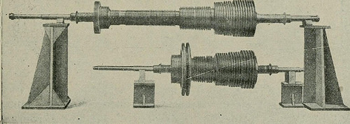
Image by Web Archive Book Pictures
Identifier: officialproceedi14rail
Title: Official proceedings
Year: 1901 (1900s)
Authors: Railway Club of Pittsburgh
Subjects: Railway Club of Pittsburgh Railroads
Publisher: Pittsburgh, Pa. : The Club
Contributing Library: Carnegie Library of Pittsburgh
Digitizing Sponsor: Lyrasis Members and Sloan Foundation
View Book Web page: Book Viewer
About This Book: Catalog Entry
View All Images: All Photos From Book
Click right here to view book on-line to see this illustration in context in a browseable online version of this book.
Text Appearing Prior to Image:
placed a largenumber of rows of Parsons blading with equivalent economy,since in the smaller sized powers it was essential in the straightParsons machine, on account of total peripheral admission, tomake the blade speeds comparatively low in order that their heightmight be as massive as practicable, to lessen the proportions ofleakage by the end of the blades due to the required blade clear-ances. Such a construction of spindles is shown in Fig. 15,exactly where the comparison is clear. As this improvement proceeded, the demand for highercapacity generators elevated, and to meet this demand it wasnecessary to materially enlarge the low-stress portions ofthe turbine, which, in some instances, essential a dividing ofthe Parsons blading into two sections, commonlv identified as thedouble-flow low-pressure expansion. In 1903 Mr. Westinghouse filed his application for patenton the mixture impulse reaction double-flow turbine illus-trated in Fig. 16. With this construction the balancing pistons Fig. IS.
Text Appearing Following Image:
Rotors of Two 500-Horsepower Steam Turbines: Upper Spindle With Complete Reaction Blading Lower Spindle ith Impulse and Reaction Blading. 89 reqniri.(l l)v the straight Parsons machine have been completely dispensedvith, and whilst for dotible-flow building twice the numberof blades have been needed as for comparable circumstances with single-flow, however the application of the impulse wheel to the higher-pres-sme stages created attainable, in a great many situations, the propermechanical style, on account of the considerable shorteningof the turbine due to the introduction of the impulse wheel,therefore permitting a length of spindle and cylinder of propermechanical stability. As this improvement progressed it was located advisable, onthe score of efficiency, to resort to the Acstinghouse singledouble-flow building. This diliers from the straight double-flow principle in using a single Curtis impulse wheel withtwo rows of revolving i)la(les. followed bv a single barrel of
Note About Photos
Please note that these pictures are extracted from scanned web page photos that may have been digitally enhanced for readability – coloration and appearance of these illustrations may possibly not completely resemble the original function.