A handful of good turbine blade machining pictures I discovered:
Image from page 483 of “The steam-engine and other heat-motors” (1909)
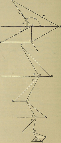
Image by Internet Archive Book Images
Identifier: steamengineother01crei
Title: The steam-engine and other heat-motors
Year: 1909 (1900s)
Authors: Creighton, William Henry Paul, 1859-
Subjects: Steam-engines Heat-engines
Publisher: New York, J. Wiley & sons [and so on., and so on.]
Contributing Library: The Library of Congress
Digitizing Sponsor: The Library of Congress
View Book Web page: Book Viewer
About This Book: Catalog Entry
View All Images: All Pictures From Book
Click here to view book on the web to see this illustration in context in a browseable on the internet version of this book.
Text Appearing Prior to Image:
ake the figures given for the water consumption of the De Laval, Rateau, and Curtis wheels and evaluate them with the final results obtained for corresponding powers and pressures of the AVestinghouse-Parsons turbine we will uncover that they are practically the exact same. In producing comparisons care have to be taken to evaluate turbines of related dimensions ! operating at equal energy. In turbines, only the delivered or brake horse-energy is measured. As the friction is practically the I identical at all powers, it is evident that at low powers the water i consumption will be excessive when compared to that at higher ones > of the identical machine. t Fig. 241. The turbine-blade may be sketched in if we have thevelocity of entrance AB, the peripheral velocity CB, and the bL de-angle J. For AC will be the angle of the back of the blade at entrance,and if there is no friction CD = AC will be the relative and CE the * Trans. A. S. M. E., Vol. XXV, p. 788f Ibid. p 774. 462 THE STEAM-ENGINE AND OTHER HEAT-MOTORS. A
Text Appearing Following Image:
Figs. 241 and 242. (From Thomas Steam-turbines.) SUPERHEATED STEAM AND STEAM-TURBINES. 463 absolute velocity of departure, as DE = CB. For a series of buckets,as in the Curtis turbine, exactly where AB represents the initial velocityand NP the final velocity a diagram related to Fig. 179 may bedrawn. In this theoretical diagram AC = CD, EK = KL} and so on. Ifthe friction is to be regarded then CD = (1 – f)AC, KL = (1 -f)EK,and so on., where /, / are the coefficients of friction.Stodola has the following (Fig. 243):
Note About Images
Please note that these images are extracted from scanned web page images that could have been digitally enhanced for readability – coloration and look of these illustrations may possibly not completely resemble the original operate.