Verify out these turbine machining international photos:
Image from web page 561 of “The Street railway journal” (1884)
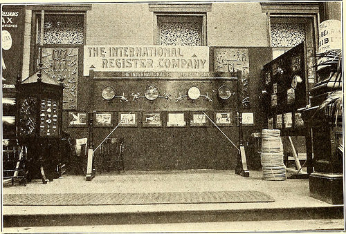
Image by Web Archive Book Images
Identifier: streetrailwayjo221903newy
Title: The Street railway journal
Year: 1884 (1880s)
Authors:
Subjects: Street-railroads Electric railroads Transportation
Publisher: New York : McGraw Pub. Co.
Contributing Library: Smithsonian Libraries
Digitizing Sponsor: Smithsonian Libraries
View Book Page: Book Viewer
About This Book: Catalog Entry
View All Photos: All Photos From Book
Click here to view book on the web to see this illustration in context in a browseable on-line version of this book.
Text Appearing Before Image:
r the excursion. A number of delegates also produced the occasion to take several ofthe appealing trips which are so quite a few in the vicinity of Sara-toga. Amongst these almost certainly the most popular of the brief excur-sions was that to Saratoga Lake, and the National Electric Com-pany contributed to the pleasure of a number of the delegates byengaging numerous automobiles and generating this run often dur-ing the convention. ♦♦♦ STEAM TURBINES FOR Extended ISLAND CITY The Westinghouse Machine Company has secured the orderfor the largest turbo-generators in the world. These will be in-stalled in the Lengthy Island City energy residence of the new Pennsyl-vania terminal, and will consist of 3 SSO0-kw turbo-generatorunits. EXHIBITS AND EXHIBITORS AT SARATOGA The exhibition of apparatus in connection with the conventionswas relatively representative, though the neighborhood situations created itimpossible to show heavy machinery in operation, and this de-tracted somewhat from the worth of the- display as a entire.
Text Appearing Following Image:
EXHIBIT OF THE INTERNATIONAL REGISTER Organization Fonda, Johnstown & Gloversville Railway, of Gloversville, N. Y.,but was unable to comprehensive them in time. These vehicles are of avery modern day sort, and were described in detail in the Souveniredition of the Street Railway Journal. THE FRANKLIN ROLLING MILL &FOUNDRY Company, of Franklin, Pa.,manufacturer of the tripartite steel pole, had oneof its three-part street poles on exhibition. Thesepoles are produced by rerolling old rails, and a givenstrength of pole can be produced at significantly less cost than ina tubular pole. G. V. A. Conger, superintendentof the pole department, was in charge of the ex-hibit, where sections of metal utilized in variousweights of pole were shown, as nicely as a single full-sized pole. THE INTERNATIONAL REGISTERCOMPANY, of Chicago, was represented by A.H. Woodward, president John Benham, vice-president W. H. Brown, secretary, and F. B.Hall, master mechanic. Neatly displayed weresamples of the well-recognized normal kinds ofNew Haven and In
Note About Images
Please note that these pictures are extracted from scanned page images that may have been digitally enhanced for readability – coloration and look of these illustrations may possibly not completely resemble the original operate.
Image from web page 411 of “Cassier’s magazine” (1891)
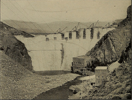
Image by Internet Archive Book Photos
Identifier: cassiersmagaz401911newy
Title: Cassier’s magazine
Year: 1891 (1890s)
Authors:
Subjects: Engineering
Publisher: New York Cassier Magazine Co.
Contributing Library: Smithsonian Libraries
Digitizing Sponsor: Smithsonian Libraries
View Book Web page: Book Viewer
About This Book: Catalog Entry
View All Photos: All Images From Book
Click here to view book online to see this illustration in context in a browseable on-line version of this book.
Text Appearing Ahead of Image:
revolutionsper minute under a head of 146 feet.They consist of three primary parts—namely, the revolving element, thestationary vanes or blades mountedin the turbine casing, and the con-trolling apparatus. The four gener-ators are of Basic Electric make.They are 3-phase, 40-cycle, 16-polevertical machines, every generatorhaving an output of 3,000 kilowattsand four,400 volts. at the base is about 30 feet. Both ofthe height and thickness of the damdiminish near the south shore, wherethe river bed is greater. The powerhouse connected with this dam has aninstallation in each flume of a 57-inchdouble runner reaction turbine of thehorizontal Francis variety. The wheelsdischarge into a frequent draft chestlocated among the runners, and theamount of water which is admittedto the wheels is controlled by wicketgates mounted in a ring about therunners and operated by a commonrotating shaft which is geared to thegovernor in the generating area.When operating beneath a 35-foot head 4oo CASSIERS MAGAZINE
Text Appearing After Image:
VIEW OF ROOSEVELT DAM Under Construction. THE Energy Home FURNISHING Current ISSEEN IN FOREGROUND the turbines develop three,000 horse-power, and when the water is drawndown to a 24-foot head the output isreduced to 1,750 horse-energy. Thegenerator gear consists of two1,800-kilowatt, four,400-volt generators,direct coupled to the turbine shafts.The machines are of the horizontalshaft, two-bearing revolving fieldtype, developed for waterwheel drive,and are provided with an exciter. These two stations, deriving theirpower from one particular small river, serve in-dustries in the two cities talked about,as nicely as furnishing illumination.The whole improvement was designedand constructed by Messrs. Viele,Blackwell & Buck, of New York thehydraulic machinery was supplied byS. Morgan Smith Organization, of York,Pa., and all the electrical apparatusby the General Electric Business. The International group of powerplants that use the head of waterat Niagara have a combined horse-energy greater than any in th
Note About Photos
Please note that these images are extracted from scanned web page images that could have been digitally enhanced for readability – coloration and appearance of these illustrations could not completely resemble the original work.