Image from page 155 of “The manufacture of pulp and paper : a textbook of modern pulp and paper mill practice” (1921)
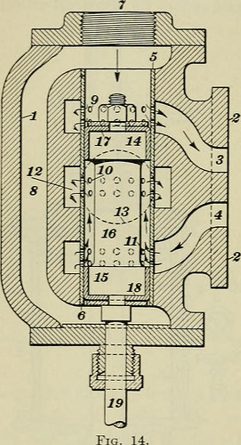
Image by Net Archive Book Images
Identifier: manufactureofpul03join
Title: The manufacture of pulp and paper : a textbook of contemporary pulp and paper mill practice
Year: 1921 (1920s)
Authors: Joint Textbook Committee of the Paper Market Stephenson, J. Newell
Subjects: Papermaking Wood-pulp
Publisher: New York : McGraw-Hill Book Company
Contributing Library: NCSU Libraries
Digitizing Sponsor: NCSU Libraries
View Book Page: Book Viewer
About This Book: Catalog Entry
View All Photos: All Images From Book
Click right here to view book online to see this illustration in context in a browseable on the web version of this book.
Text Appearing Prior to Image:
six is shown, withleather packing cups at heads ofthe valve at 17 and 18 thesecups type a water-tight jointbetween the moving valve pistonand the brass tube. The motionof the valve piston is controlled by means of valve rod 19. In Fig. 14. the valve piston is so set that high-pressure water ispassing through holes 9. and into the top of the hydraulic cylinder,by means of port 3. At the identical time, the valve position is such thatthe water contained in cylinder beneath piston is passing throughport four. through holes 11, along in between valve spindle 16 and theinside of the circular brass tube, out through holes ten into outletports 12, and then to valve outlet 13. When the wood is com-pletely ground in the pocket, the valve rod 19 is pushed up by alever, so that valve finish 15 is above port four. This makes it possible for higher-stress water to pass into the cylinder at four, causing the pistonto rise in the hydraulic cylinder. Water is discharged from topof the hydraulic cylinder at three and out of valve at 13, as prior to.
Text Appearing Right after Image:
Fig §3 GRINDERS AND GRINDING 27 The total region of every single of the sets of holes 9, ten, and 11 has animportant effect on the price of movement of the hydraulicpiston, on the back stress brought on by the discharging water, andon the price of water consumption. A study of the example in Art.48 will allow the reader to interpret these variables. 44. Sharpening Devices.—There areseveral distinct kinds of devices madefor sharpening and trueing-up thesurface of grindstones. They may bedivided, according to the constructionof the sharpening device, into threegroups: the hand-operated stick themechanical-feed lathe and thehydraulic-feed lathe. The hand-operated stick is produced ofan iron or wooden deal with 1, Fig. 15,with iron straps two bolted upon thesides. The burr 3 revolves on ashaft four, the axis of which coincideswith the axis of the burr. With thissharpening device, the quantity oftreatment and price of treatment de-pend upon how hard the operatorpresses the burr against the stone andupon how quickly h
Note About Photos
Please note that these photos are extracted from scanned web page images that may have been digitally enhanced for readability – coloration and appearance of these illustrations could not completely resemble the original function.