Some cool four axis milling photos:
Image from web page 300 of “The terrestrial air-breathing mollusks of the United States, and the adjacent territories of North America:” (1857)
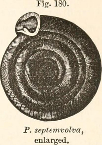
Image by Internet Archive Book Photos
Identifier: terrestrialairbr05abinn
Title: The terrestrial air-breathing mollusks of the United States, and the adjacent territories of North America:
Year: 1857 (1850s)
Authors: Binney, Amos, 1803-1847 Binney, W. G. (William Greene), 1833-1909 Gould, Augustus A. (Augustus Addison), 1805-1866
Subjects: Pulmonata Mollusks — North America
Publisher: Boston, C. C. Small and J. Brown
Contributing Library: MBLWHOI Library
Digitizing Sponsor: MBLWHOI Library
View Book Web page: Book Viewer
About This Book: Catalog Entry
View All Pictures: All Images From Book
Click here to view book on the internet to see this illustration in context in a browseable on the web version of this book.
Text Appearing Prior to Image:
Text Appearing Following Image:
POLYGYRA. 281 In the area of the Rio Grande, each in Texas and Tamaulipas. A speciesof the Texan Subregion.Animal not observed. Polygyra septemvolva, SAY. Shell broadly umbilicated, subcarinated, discoidal, Fjg. russet horn-colour, with stout striae above, smooth be-low plane above, with 7 (sometimes 8|) or much less flat-tened whorls equally plane under, with 3^ full, moreconvex whorls on a level, then ending in a deep, per-vious umbilicus, the penultimate somewhat overlappedby the last, the antepenultimate considerably the largestaperture really oblique, remote from the axis, subreni-form, constricted behind the peristome peristomethickened, bluntly reflected, continuous, its termina-tions joined by an elevated, heavy, tooth-like triangularfold. Higher diameter 15, lesser 13 mill. height, 4 mill. Polygyra septemvolva, SAY, Journ. Acad. Nat. Sci. Phila., I. 278 (1818) Nich. Encycl., 3d ed. (1819) BINNEYS ed. 11. — TRYON, Am. Journ. Conch., III. 159 (1867).Helix septemvolva, BINNEY, Ter
Note About Images
Please note that these photos are extracted from scanned web page images that might have been digitally enhanced for readability – coloration and appearance of these illustrations could not completely resemble the original function.
Image from web page 39 of “Official proceedings” (1901)
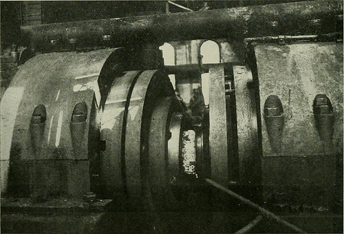
Image by Internet Archive Book Pictures
Identifier: officialproceedi14rail
Title: Official proceedings
Year: 1901 (1900s)
Authors: Railway Club of Pittsburgh
Subjects: Railway Club of Pittsburgh Railroads
Publisher: Pittsburgh, Pa. : The Club
Contributing Library: Carnegie Library of Pittsburgh
Digitizing Sponsor: Lyrasis Members and Sloan Foundation
View Book Web page: Book Viewer
About This Book: Catalog Entry
View All Images: All Pictures From Book
Click right here to view book on-line to see this illustration in context in a browseable on the internet version of this book.
Text Appearing Just before Image:
FIG. 4. By means of a steel dog running amongst two rails, the disc 17 is transferred to a hydraulic press whose function is to pieree ahole significantly smaller sized than the rough bore preferred about haltway by way of the center on the axis of the disc in order that thedisc can be held among the rolls, on a pin. till the hydraulicpressure applied grips the piece and forging commences ( SeeFigure five). The Mills were designed and patented by Mr. E. E.
Text Appearing Right after Image:
FIG. 5. Slick and are exclusive in that they are the iirst of their type everbuilt and are original in each respect. Every single mill, of whiclithere are two, is composed of two rolls or dies facing eachother, set on the ends of two shafts which are out of line onemill getting the shafts a])proximately 14 and the other approxi-matelv 7^ out of parallel. It is evident as a result that when thedies are brought collectively ahead of the shafts turn, the disc is stib-ject to a forging action. Mien enough forging has takenplace under a hydraulic pressure beginning at about 700.000pounds and intensiiied to 3.000.000 pounds maximum at thefinish in the bigger mill, to begin the piece into the contour ofthe die, steam energy furnished by a 2500 H. P. engine is appliedto revolve the roll shaft and from this point till the piece istaken from the rolls, it is topic to each rolling and forgingaction wdiich insures close grained, nicely worked metal. In passing, it is interesting to note the further heavy equip-
Note About Pictures
Please note that these images are extracted from scanned page photos that may have been digitally enhanced for readability – coloration and look of these illustrations may possibly not perfectly resemble the original perform.
Image from page 675 of “A text-book of mycology and plant pathology” (1917)
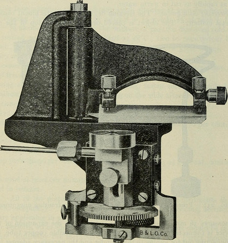
Image by World wide web Archive Book Photos
Identifier: textbookofmycol00hars
Title: A text-book of mycology and plant pathology
Year: 1917 (1910s)
Authors: Harshberger, John W. (John William), 1869-1929
Subjects: Plant diseases Fungi
Publisher: Philadelphia : P. Blakiston’s Son & Co.
Contributing Library: University of British Columbia Library
Digitizing Sponsor: University of British Columbia Library
View Book Page: Book Viewer
About This Book: Catalog Entry
View All Photos: All Pictures From Book
Click right here to view book on-line to see this illustration in context in a browseable online version of this book.
Text Appearing Prior to Image:
table or physicians microtome(Figs. 231, 232). An ether attachment is also employed (Fig. 233). LESSON 44 Use of Drawing and Projection Apparatus.—The author has found it an excellenttraining for students to understand the use of the drawing apparatus developed by Edinger,as well as the new Spencer photomicrographic camera. These pieces of apparatuscan be employed for drawing, for projection and for photomicrography.42 658 LABORATORY Workouts The Edinger drawing and projection apparatus^ (Figs. 234, 235) projects micro-scopic objects even beneath a high magnification straight upon the drawing board sothat the outUne can be traced in pencil. The image therefore projected can be used fordemonstrating to a little audience and also for photomicrography. For such worka strong illuminant is utilized with a hand-fed electric arc taking four amperes. It possibly employed with a appropriate plug connected with the direct-present residence supply (alter-nating Current could be employed by particular arrangement). The crater in the optimistic
Text Appearing Following Image:
L..C0.Fig. 232.—Clinic microtome with freezing attachment. carbon from which light emanates is brought to coincide with the optic axis of theapparatus by m^eans of the two screws (a) as in Fig. 234, and the lamp with the con-densing method K can be moved along the optic axis by the lever G. The distancebetween the carbons is regulated by the milled head (b) which if out of attain ofthe operator can be turned by the lengthy deal with connected to (c). The smaller automobile-bon which is placed horizontally need to not project into the optical axis, or craterarea of the bigger vertical carbon. The apparatus suitable consists of a cast-iron pillar S, Fig. 234, mounted upon a1 May possibly be had of E. Leitz, 30 East i8th Street, New York City. LABORATORY AND TEACHING Strategies 659 rectangular frame into which a drawing board is fitted. The fitting is grooved toallow the adjustment of the illuminant L by the lever G, the stage O, and the objec-tive holder H, the face being graduated to H cm. in order that the cor
Note About Pictures
Please note that these images are extracted from scanned web page photos that could have been digitally enhanced for readability – coloration and appearance of these illustrations may possibly not perfectly resemble the original perform.