Some cool four axis milling photos:
Image from page 873 of “Farrow’s military encyclopedia : a dictionary of military expertise” (1885)
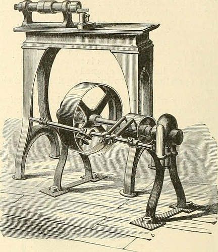
Image by Net Archive Book Images
Identifier: farrowsmilitarye02farr
Title: Farrow’s military encyclopedia : a dictionary of military knowledge
Year: 1885 (1880s)
Authors: Farrow, Edward S. (Edward Samuel), b. 1855
Subjects: Military art and science
Publisher: New York : [s.n.]
Contributing Library: University of California Libraries
Digitizing Sponsor: Web Archive
View Book Page: Book Viewer
About This Book: Catalog Entry
View All Images: All Photos From Book
Click here to view book online to see this illustration in context in a browseable on the internet version of this book.
Text Appearing Just before Image:
rsts into a flame : Strik-er, major-spring, indicator, extractor, sight-spring,catch-block spring, trigger-spring, block-axis pin,ex-tractor-axis, sight-slide, and steel screws, etc. Thefollowing elements are l)lued Up]>er and lowerbands, upper and decrease hand-pins, guard and tjandswivels, fore-end hook-screws, sight-leaf, lever catch-block and pin, guard, nose-cap, the rod-holder, etc.They arc polished, cleaned with lime to remove allgrease, and are then covered with powdered char- coal and raised to a temperature of about 550° Fah-renheit. A milling-machine and a screw-head slotter com-bined, arranged for taking the quick milling cuts, isshown in Fig. 3. The box-shaped head is placed ona planed iron table, which is surrounded by a grooveto catch oil and chips. The cross slide is adjustedby a screw that projects in front, and squared by awrench. The sliding-table is operated for a handlever and the motion is gauged by an adjustablestop behind. A vertical movement is commimicat-
Text Appearing Right after Image:
Fig.5. ed to the knee slide by means of a rack and gear,operated by a hand lever in front, as shown in thedrawing. For slotting screws, a sliding vise is fur-nished, so arranged that the front or movable jawtightens on the screw to be slotted by signifies oftwo springs beneath the jaw. The jaw is linked sothat it is operated wholly by the hand lever whichfeeds the vise. With the machine with the leververtical motion, screws can also be fed up below thesaw which significantly increases its capacity. Counter-shaft has adjustable self-oiling hangers. Fig. four, re-presents the usual kind of slotting-machine, suppliedwith slotting-bar counter-balances, so as to run with-out jarring. It is driven by a variable crank, withquick, return motion has bearing for slotting-baradjustable vertically, to suit the diilerent heights ofwork has compound tables, with circular plate andcentering stud and the feed is self-acting, so as tobe perfectly balanced. Fig. five, represents the screwpolishing machine, with bea
Note About Pictures
Please note that these images are extracted from scanned page pictures that may have been digitally enhanced for readability – coloration and appearance of these illustrations may possibly not completely resemble the original work.
Image from page 230 of “The Artizan” (1843)
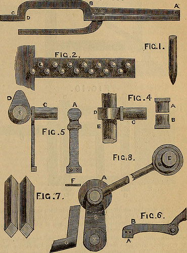
Image by Net Archive Book Pictures
Identifier: artizan231865arti
Title: The Artizan
Year: 1843 (1840s)
Authors: Artizan club (London, England)
Subjects: Technologies Industrial arts
Publisher: [London : Simpkin, Marshall, and Co.]
Contributing Library: Smithsonian Libraries
Digitizing Sponsor: Smithsonian Libraries
View Book Web page: Book Viewer
About This Book: Catalog Entry
View All Pictures: All Pictures From Book
Click here to view book on-line to see this illustration in context in a browseable online version of this book.
Text Appearing Just before Image:
tes, the jawsthemselves getting attached to springs which have a tendency to open them,and possessing grooves of semicircular section to obtain tbe wire to beoperated upon. C is the die which produces the head, in the centre of itsface is sunk n cup shaped depression, corresponding to the form of head tobe produced. I) is the cam by which it is driven against the wire finish,which is carried by a stout shaft E. Figure I is B strategy, and figure 5 a sideelevation of this arrangement in the latter the jaw Ii is removed, to show the form of groove in the jaw A. The head obtaining been partlyformed by the first blow of the die C, the jaws A B release the wire sothat it may be advanced sufficiently for completion, when a second blowfrom C finishes the head. The pin is subsequent reduce off to its correct length bya shear, figure 6. This shear is fixed upon an axis C, surrounded by ahelical spring which holds up the arm B C, to the end B of which thekeen cutting edge A is attached. When the pin has been headed, a cam FIC.three.
Text Appearing Right after Image:
striking the end D of the shear depresses the cutting edge A, and socauses it to cut off the pin close to the jaws (A B, figure 4). The function sofar finished falls down into an inclined pair of rails shown partly insection in figure 7 among these the pins are supported by the heads,and they steadily slide down to the pointing mill. As the pins arriveat the bottom of the rails they are received in a equivalent channel, runningacross the finish of the machine parallel to the pointing mill, figure eight. Arepresents the grinding roller, which is coated with file-like surfaces ofhard steel bent to match on to its periphery, and there secured by suitablebelts, against which the points of the pins are pressed by a sliding pieceF, actuated by a lever connected with a cam or swash plate on one ofthe tarn shafts, the movement of the sliding piece rolls the pins roundso that the points are uniformly ground, but it is so arranged that atevery alternate back stroke it rides clear of the perform, so that the
Note About Pictures
Please note that these pictures are extracted from scanned page pictures that may possibly have been digitally enhanced for readability – coloration and look of these illustrations may not perfectly resemble the original function.
Image from page 126 of “Lumber, its manufacture and distribution” (1922)
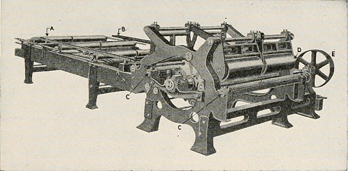
Image by World wide web Archive Book Photos
Identifier: lumberitsmanufac00bryauoft
Title: Lumber, its manufacture and distribution
Year: 1922 (1920s)
Authors: Bryant, Ralph Clement, 1877-
Subjects: Lumber Lumber trade — United States
Publisher: New York Wiley
Contributing Library: Earth Sciences – University of Toronto
Digitizing Sponsor: MSN
View Book Web page: Book Viewer
About This Book: Catalog Entry
View All Photos: All Photos From Book
Click here to view book online to see this illustration in context in a browseable online version of this book.
Text Appearing Just before Image:
. In a mill sawing common-length logs it is from 25 to 30 feet 1 The location of the edger on the sawing floor of a sawmill is shown in Fig. 24. THE EDGER 99 in length. Where very extended logs are handled the length must beincreased accordingly. The framework of the edger suitable is cast andsupports the saw arbor, feed roll, press roll, driving pulleys and sawshifting devices. The saws are mounted on an arbor which has two opposite rectan-gular-shaped lugs parallel to its axis and slotted methods on the saw collarsfit more than them. This approach of mounting enables the edgerman to movethe saws in a lateral path when it is desired to enhance or decreasethe distance among them. The quantity of saws carried on the arborvaries from two to four on a single-gang edger fed by 1 man, and fromsix to eight saws on a double-gang edger fed by two guys. A single or twosaws on the outer ends of the arbor are typically stationary on medium-sized edgers. These saws are set either 4 or 6 inches inside of the side
Text Appearing Soon after Image:
By permission The Prescott Co. Fig. 72.—A Double Gang Edger. A. Front Feed Table. B. Side Guide. C. FeedRolls. D. Press Rolls. E. Feed Roll Drive. guides, so that when the latter are flush with the inner edge of the fronttable frame, a 4- or a six-inch strip will be produced. The remaining sawsmay be moved from side to side, coming within four inches of the station-ary saws or of every single other. The movable saws are shifted in a lateral direction by means of asteel U-shaped guide, Fig. 73, which fits around the outer edge of thesaw under the cutting line. These guides, which are equipped withrenewable hardwood guide plugs, A, which steady the saw, are hingedin order that they may possibly be thrown back out of the way when the sawsare removed from the arbor. The saw guide shown in Fig. 73, is mounted on a planed iron guideplate B, from 30 to 48 inches long which slides in planed approaches. Theseguide plates are moved by a steel flat-hyperlink chain C, which is woundaround the chain drum D on the end of the shiftin
Note About Pictures
Please note that these pictures are extracted from scanned web page photos that could have been digitally enhanced for readability – coloration and look of these illustrations may not perfectly resemble the original perform.