Some cool 5 axis machine shop photos:
Image from web page 570 of “Railway mechanical engineer” (1916)
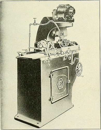
Image by Net Archive Book Photos
Identifier: railwaymechanica94newy
Title: Railway mechanical engineer
Year: 1916 (1910s)
Authors:
Subjects: Railroad engineering Engineering Railroads Railroad cars
Publisher: New York, N.Y. : Simmons-Boardman Pub. Co
Contributing Library: Carnegie Library of Pittsburgh
Digitizing Sponsor: Lyrasis Members and Sloan Foundation
View Book Web page: Book Viewer
About This Book: Catalog Entry
View All Images: All Images From Book
Click here to view book on the internet to see this illustration in context in a browseable on-line version of this book.
Text Appearing Ahead of Image:
rs due to the blacksmith type- August, 1920 RAILWAY MECHANICAL ENGINEER 551 ing the 30 degree angle on each and every link by hand. Cutting thestock at any angle is made feasible by the use of suitabledies. The dies essential depend upon the kind of function de-sired to be accomplished and they are crucial specifically in cut- ting round stock. With the dies, it is feasible to cut roundstock well within five per cent of the perpendicular and theend of the stock is not deformed. This feature is particu-larly beneficial for particular sorts of perform. Motor-Driven Automatic Hob Grinder THE most recent addition integrated in the line of precisiongrinding machines manufactured by tlie H. E. HarrisEngineering Organization, Bridgeport, Conn., is an auto-matic hob grinder. This machine is furnished either as abelt- or motor-driven machine, the former being named No.815-B and the latter No. 815-M. On account of the manyadvantages of machines equipped with unit motor drive theNo. 815-M machine illustrated is a favourite with shop fore-
Text Appearing Right after Image:
Harris Automatic Hob Grinder Arranged for Motor Drive guys and managers. It can be set up in the most convenientposition, irrespective of shaft or group drive. The motor for driving the wheel spindle is mounted aboveand upon a circular horizontal slide, the wheel head beingmounted under on the identical slide. The drive from motorspindle to wheel spindle is by an endless belt, the slack beingtaken up by raising the motor itself. This motor does nowork except to drive the spindle and sudden torques fromreversing or inde.xing do not affect it. The cutting face ofthe grinding wheel coincides with the vertical axis of thehorizontal circular slide, so that when this slide is swiveledto the preferred angle of the hob flute, the wheel is in the cor-rect position. The weight of the motor adds to the stabilityof the machine and helps in absorbing viljration. Better re-sults can be secured witli this type than with the belt-drivenmachine. The ball crank handles, shown on the correct ofthe column, manage
Note About Photos
Please note that these pictures are extracted from scanned page photos that might have been digitally enhanced for readability – coloration and look of these illustrations may not perfectly resemble the original function.