Some cool machining turbine rotors pictures:
Image from web page 223 of “Steam turbines a sensible and theoretical treatise for engineers and students, such as a discussion of the gas turbine” (1917)
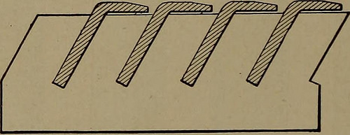
Image by Net Archive Book Images
Identifier: steamturbinespra00moye
Title: Steam turbines a sensible and theoretical treatise for engineers and students, including a discussion of the gas turbine
Year: 1917 (1910s)
Authors: Moyer, James Ambrose, 1875-
Subjects: Steam-turbines
Publisher: New York, Wiley
Contributing Library: The Library of Congress
Digitizing Sponsor: The Library of Congress
View Book Web page: Book Viewer
About This Book: Catalog Entry
View All Images: All Pictures From Book
Click here to view book on the web to see this illustration in context in a browseable on the web version of this book.
Text Appearing Before Image:
pe of blading for Parsons turbines, patented by H. R.Sankey in 1903, has been applied with particular modifications inthe Allis-Chalmers and the Willans turbines. A typical illus-tration of this blading is shown in Fig. 97. It is distinguished 204 THE STEAM TURBINE principally from the usual Parsons blading by the attachment ofa U-shaped shroud ring, B, around both the moving and thestationary blades. The blades are reduce to the needed length from bars of copperalloy drawn, like wire, to a appropriate shape. After the bladesare reduce from the bar, they are formed in machine tools ofspecial design and style, so that at the root they have an angular dove-tail shape as illustrated in the figure, exactly where the blades are showninserted in a suitable foundation ring, A. After this foundationring is turned to the suitable diameter, dovetail slots for theblades (see Fig. 98) are reduce by a special milling machineintended for really accurate spacing and inclination so as to givethe essential pitch and angle to the blades.
Text Appearing Following Image:
Fig. 98. Spacing for Sankeys Blading. Soon after the roots of the blades have been inserted in the founda-tion rings, which, in cross-section, are also of a dovetail shape,the rings are inserted into corresponding grooves in the drumsof the rotor and in the inside of the casing exactly where they are held inplace by essential pieces. Every of these important pieces following beingdriven into place is upset in an undercut groove which serves as alocking device. The dovetail shapes employed in this constructionmake the attachment of the blades at their roots extremely secure. The channel-shaped shroud rings are purposely made thin atthe flanges so that in case of contact amongst the revolving andstationary components these flanges will be worn off at their edgeswithout tearing out or bending the blades. By this technique, aswell as with all other varieties of shroud ring building, the strengthof the blading depends, not on the strength of a single blade,but on the total strength of as numerous blades as are bound collectively.In the Allis-C
Note About Photos
Please note that these photos are extracted from scanned page images that may possibly have been digitally enhanced for readability – coloration and appearance of these illustrations may not completely resemble the original operate.