")
Verify out these pump impeller machining photos:
Image from page 135 of “The Santa Fe magazine” (1913)
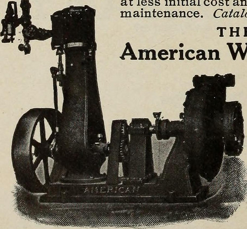
Image by Web Archive Book Photos
Identifier: santafemagazine5101unse_three
Title: The Santa Fe magazine
Year: 1913 (1910s)
Authors:
Subjects: Atchison, Topeka, and Santa Fe Railroad Business Railroads
Publisher: Chicago : Santa Fe Magazine
Contributing Library: University of Illinois Urbana-Champaign
Digitizing Sponsor: University of Illinois Urbana-Champaign
View Book Web page: Book Viewer
About This Book: Catalog Entry
View All Images: All Pictures From Book
Click here to view book on the web to see this illustration in context in a browseable on the internet version of this book.
Text Appearing Just before Image:
TSMOUTH STEEL, CO. Executive OfficesWHEELING,W. VA. Operating and Sales Dept.PORTSMOUTH,OHIO THE MOST EFFICIENTRAILROAD PUMP is the centrifugal for the cause that it raisesmore water with much less power and requires lessattention than any other style of pump. American 99 Centrifugal PUMPS provide 25 to 33percent much more water with thesame energy than old style centrifugals. The purpose is the impeller is accurately machined tothe casing- with a excellent reduce-off at the outlet, making- itimpossible for water to pass the discharge pipe and berepumped, and there is no sudden change of directionof the water in passing thru the pump. The single stage pump operates against heads up to125 feet, the two-stage up to 250 feet, the four-stage up to500 feet, and can be operated in any location exactly where aduplex steam pump can be installed,at significantly less initial price and less expense ofmaintenance. Catalog for the asking. THE American Effectively Performs Common Officeand Operates: Aurora,I11.,U.S.A. Chicago OfficeFirst Nat. Bank
Text Appearing Right after Image:
High Grade Iron A trial of CARTER SPECIALStaybolt Iron will convince you ofits merits. Not first cost, but ultimateresults. Attempt it and examine with for-eign irons. You will be shocked,no doubt. Christopher Murphy & Co. Peoples Gas BuildingCHICAGO, ILL. GUILFORD S. WOOD Wonderful NORTHERN Developing : CHICAGO
Note About Images
Please note that these images are extracted from scanned web page images that could have been digitally enhanced for readability – coloration and appearance of these illustrations may not perfectly resemble the original function.
Image from web page 193 of “Transactions of the Institution of Mining Engineers” (1898)
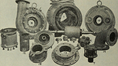
Image by Web Archive Book Photos
Identifier: transactionsofin6162inst
Title: Transactions of the Institution of Mining Engineers
Year: 1898 (1890s)
Authors: Institution of Mining Engineers (Wonderful Britain)
Subjects: Mineral industries
Publisher: Newcastle-upon-Tyne : The Institution
Contributing Library: University of Illinois Urbana-Champaign
Digitizing Sponsor: University of Illinois Urbana-Champaign
View Book Page: Book Viewer
About This Book: Catalog Entry
View All Pictures: All Pictures From Book
Click here to view book on the internet to see this illustration in context in a browseable on the web version of this book.
Text Appearing Before Image:
ereis full continuity of insulation throughout every phase of the winding.The star point is very carefully spliced and vulcanized in a special mould. Inthis type of machine the cost-free ends of each phase are brought out througha stuffing-box on the motor-frame for a length of about 50 feet, and thereterminate in a three-pole watertight coupling, to which reference willbe created once again. The extended cables are protected by armoured rubberhose. The overhangs of the coils are clamped securely to the motor-physique. The iron core-plates of each stator and rotor are treated with aspecial varnish, each plate becoming passed through a machine resemblinga domestic mangle, the rollers of which revolve in the liquid. By thismeans an even layer of varnish of mimimum thickness is applied to eachplate, hence effectively sealing the joints in the assembled core. (2) is therotor and shaft, and (eight) the impeller already referred to. (three) and (4)are steel roller-bearings for the radial load, and are mounted in gunmetal
Text Appearing Soon after Image:
Fig. 7.—Component Parts of MoTOR-puMr shown in Fig. six. 1920-1921.] IIAMSAY SUBMERSIBJ.E ELECTRIC MOTORS. 173 housings (6) and -(T). (5) is a double-thrust ball-bearing, which locatesthe rotor axially and takes the thrust due to the pump. This bearingis mounted with a single radial bearing in housing (7), and the whole iscarried in the motor finish-bracket (ten). The housing (six) is carried inthe volute casing (9), which types the other finish-bracket of the motor. The water-channel within the volute is of common design and style, withgradually growing sectional regions in the path of rotaton of theimpeller. The boundary-line of the volute is such that it conforms to theactual angle of discharge of the water from the impeller. (11) is a filter-physique attached to the discharge flange, and into the centre of this bodyis fitted a brass cylinder (12), the inside diameter of which is equal tothe diameter of the discharge-pipe. The function of this filter will be rrn
Note About Images
Please note that these pictures are extracted from scanned page pictures that may have been digitally enhanced for readability – coloration and appearance of these illustrations might not completely resemble the original function.
Image from page 194 of “Transactions of the Institution of Mining Engineers” (1898)
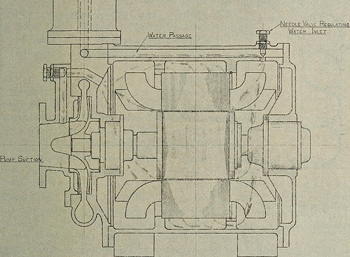
Image by Net Archive Book Photos
Identifier: transactionsofin6162inst
Title: Transactions of the Institution of Mining Engineers
Year: 1898 (1890s)
Authors: Institution of Mining Engineers (Fantastic Britain)
Subjects: Mineral industries
Publisher: Newcastle-upon-Tyne : The Institution
Contributing Library: University of Illinois Urbana-Champaign
Digitizing Sponsor: University of Illinois Urbana-Champaign
View Book Page: Book Viewer
About This Book: Catalog Entry
View All Images: All Pictures From Book
Click here to view book on the web to see this illustration in context in a browseable on the web version of this book.
Text Appearing Before Image:
Fig. 7.—Component Components of MoTOR-puMr shown in Fig. six. 1920-1921.] IIAMSAY SUBMERSIBJ.E ELECTRIC MOTORS. 173 housings (six) and -(T). (five) is a double-thrust ball-bearing, which locatesthe rotor axially and requires the thrust due to the pump. This bearingis mounted with one radial bearing in housing (7), and the complete iscarried in the motor finish-bracket (10). The housing (6) is carried inthe volute casing (9), which forms the other finish-bracket of the motor. The water-channel inside the volute is of common design, withgradually rising sectional regions in the path of rotaton of theimpeller. The boundary-line of the volute is such that it conforms to theactual angle of discharge of the water from the impeller. (11) is a filter-body attached to the discharge flange, and into the centre of this bodyis fitted a brass cylinder (12), the inside diameter of which is equal tothe diameter of the discharge-pipe. The function of this filter will be rrn
Text Appearing Right after Image:
Fig. 8.—General Arrangement of Motor-pump, with Arrows showingWater-circulation. described later. (13) is the pump suction-cover, which is attached tothe volute (9), and the bend (14) is attached to (13). (15) is a swifeig-bolt adaptor-coupling for the delivery-pipe. Cooling-water Circulation.—In Fig. 8 the arrows indicate the pathstaken by the water from the pump to the motor and back to the pump.The water in this kind of pump is taken from the filter previouslymentioned, which is mounted on the pump-discharge. The brass cylinderthrough which the water passes is offered with a large number ofopenings about f inch in length circumferentially and about 20 mills(-020 inch) in width axially. These openings lead into an annularchamber of ample dimensions surrounding the brass cylinder, in whichchamber the water moves at a quite low velocity. For this size of machine ten gallons per minute are really sufficient 174 TRANSACTIONS INSTITUTION OF MINING ENGINEERS. [VoL. LXI. for perfect coo
Note About Pictures
Please note that these photos are extracted from scanned web page images that could have been digitally enhanced for readability – coloration and appearance of these illustrations might not completely resemble the original function.