")
A couple of good machining turbine rotors photos I located:
Image from web page 290 of “Steam turbines a practical and theoretical treatise for engineers and students, including a discussion of the gas turbine” (1917)
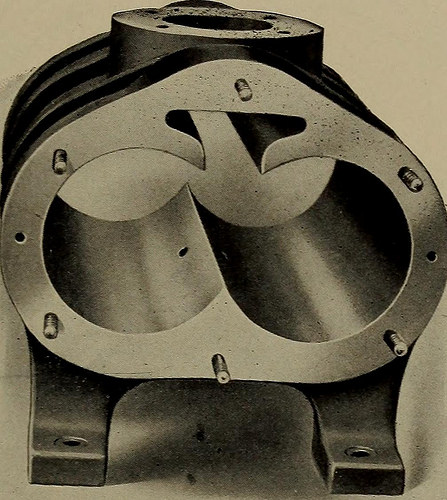
Image by Web Archive Book Images
Identifier: steamturbinespra00moye
Title: Steam turbines a sensible and theoretical treatise for engineers and students, such as a discussion of the gas turbine
Year: 1917 (1910s)
Authors: Moyer, James Ambrose, 1875-
Subjects: Steam-turbines
Publisher: New York, Wiley
Contributing Library: The Library of Congress
Digitizing Sponsor: The Library of Congress
View Book Web page: Book Viewer
About This Book: Catalog Entry
View All Images: All Pictures From Book
Click right here to view book on the internet to see this illustration in context in a browseable on the internet version of this book.
Text Appearing Just before Image:
W>^ M O a GO Industrial Varieties 271 SPIRO TURBINES.*The Spiro turbine (Fig. 157) consists just of two herringbonegear wheels which mesh with each other and revolve in a close-fittingcasing. Steam enters at the inlet pipe at the bottom and passesaround the gears in its expansion to the exhaust pipe at the top.Steam discharges from the inlet pipe through the small holes,equivalent to non-expanding nozzles shown in Figs. 158 and 159,into the pockets or spaces in between adjacent gear teeth. As
Text Appearing After Image:
Fig. 158. The Spiro Casing or Cylinder. The two holes near the central ribinside the cylinder are the steam nozzles. the rotors revolve the tooth-space occupied by the steamincreases in length as the steam expands. Finally the steamescapes when the outer ends of the teeth pass the line of contactbetween the two rotors. The enhanced length of this tooth-space from the time the steam is admitted until it is exhaustedis shown in Fig. 160, by the comparison of the length of thetooth-grooves at A with the length of the outer white lines.By obtaining the steam inlet at the bottom the weight of the rotorsis partly carried by the steam stress and friction is muchreduced under what it would be if the inlet were at the leading. * It is typically understood that a steam turbine is a machine for transformingthe velocity of steam into operate. The Spiro turbine operates only by the expansionof steam, and is as a result more properly a rotary engine. 2f2 THE STEAM TURBINE Spiro turbines are appropriate only f
Note About Pictures
Please note that these pictures are extracted from scanned web page photos that could have been digitally enhanced for readability – coloration and appearance of these illustrations may not perfectly resemble the original operate.
Image from web page 547 of “The steam engine and turbine a text-book for engineering colleges” (1911)
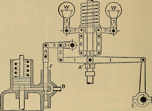
Image by Internet Archive Book Images
Identifier: steamengineturbi01heck
Title: The steam engine and turbine a text-book for engineering colleges
Year: 1911 (1910s)
Authors: Heck, Robert Culbertson Hays, 1870-
Subjects: Steam-engines Steam-turbines
Publisher: New York, D. Van Nostrand business
Contributing Library: The Library of Congress
Digitizing Sponsor: The Library of Congress
View Book Web page: Book Viewer
About This Book: Catalog Entry
View All Pictures: All Photos From Book
Click right here to view book on-line to see this illustration in context in a browseable on-line version of this book.
Text Appearing Just before Image:
ons Admission Valve and Controlling Mechanism: this is valve Vi in Fig. 25. ated by steam in the identical manner, but its pilot valve is offered only asimple displacement, with no oscillation. The governor mechanism is sketched in Fig. 378. The eccentric Eis on the same spindle with the wheel driven by the worm shown inFig. 361, and the lever 1 is oscillated as soon as to each and every so numerous revolutions, 532 Style AND Construction OF THE TURBINE. [Chap. X. say 5 or six, of the rotor. The governor getting at one particular finish of the machine,piece 3 requires the form of a extended rod or shaft, with arms keyed to it. Thefunction of the governor is merely to raise and reduce the fulcrum A. In this technique of control, the turbine has a periodic pulsation of ad-mission stress. Steam-channel locations and vane angles have been sodesigned, presumably, as to give best performance with steam of fullpressure. Most of the steam used enters in the course of the higher-pressure por-tion of the cycle period, hence operates to better effect than if at the
Text Appearing Soon after Image:
Fig. 378. — Outline of Governor and Valve Gear, Westinghouse-Parsons Turbine. equivalent imply steady stress. Against this argument should be setthe reality that a part of the steam functions at very low efficiency although thealternate acceleration and retardation of the whole steam existing cer-tainly appears most likely to exert a dangerous influence. No data are availableas to the manner in which the pulsations extend via the turbine tothe low stages, but there will evidently be a tendency to damp themout. In a numerous-stage impulse turbine, with its massive enclosed steamspaces in the wheel chambers, such modulating action would be verystrong — but the scheme is never ever used with that type of machine. As among the two systems of puff admission and steady throttling,no comparative data are extant: the distinction in net benefits is probablyso small that repeated and very cautious tests of the exact same machinewould be required to establish its existence and quantity. One particular un-doubted merit of the Parsons device
Note About Images
Please note that these images are extracted from scanned page images that may have been digitally enhanced for readability – coloration and appearance of these illustrations could not completely resemble the original function.
Image from page 291 of “Steam turbines a practical and theoretical treatise for engineers and students, such as a discussion of the gas turbine” (1917)
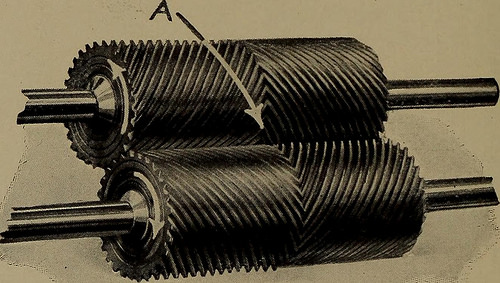
Image by World wide web Archive Book Photos
Identifier: steamturbinespra00moye
Title: Steam turbines a practical and theoretical treatise for engineers and students, including a discussion of the gas turbine
Year: 1917 (1910s)
Authors: Moyer, James Ambrose, 1875-
Subjects: Steam-turbines
Publisher: New York, Wiley
Contributing Library: The Library of Congress
Digitizing Sponsor: The Library of Congress
View Book Page: Book Viewer
About This Book: Catalog Entry
View All Pictures: All Pictures From Book
Click right here to view book on the web to see this illustration in context in a browseable on the web version of this book.
Text Appearing Before Image:
INLET Fig. 159. Section of Spiro Cylinder and Rotors at Mid-length.
Text Appearing Following Image:
Fig. 160. The Rotors. for heating buildings. Under these conditions low steam con-sumption, as would be obtainable with condensing operation, isunimportant. Sufficient expansion for condensing operation isimpracticable with this sort of turbine. Compactness is alsoan essential feature. The casing of such a turbine is alone no Industrial Types 273 bigger than the cylinder of a good high-speed engine of the samecapacity and is even smaller than comparable industrial sizesof electric motors. Governing is accomplished by throttling thesteam pressure by a technique comparable to that utilised for almost allsteam turbines of reasonably modest size (less than one hundred horsepower). CHAPTER VIII.GOVERNING STEAM TURBINES. Approaches of governing steam turbines, or, in other words, ofregulating the supply of steam to suit the load on the machine,might be classified as follows: i. Throttling or partly closing the steam admission valve. two. Varying the cross-section of the steam passages by cuttingout nozzles. 3. Varyi
Note About Pictures
Please note that these pictures are extracted from scanned page images that may have been digitally enhanced for readability – coloration and appearance of these illustrations could not completely resemble the original work.