")
Some cool 4 axis milling images:
Image from page 125 of “The Bell System technical journal” (1922)
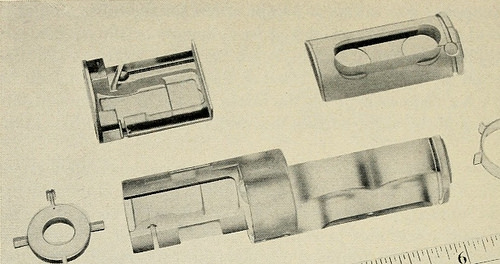
Image by Internet Archive Book Images
Identifier: bellvol36systemtechni00amerrich
Title: The Bell System technical journal
Year: 1922 (1920s)
Authors: American Telephone and Telegraph Company
Subjects: Telecommunication Electric engineering Communication Electronics Science Technology
Publisher: [Short Hills, N.J., etc., American Telephone and Telegraph Co.]
Contributing Library: Prelinger Library
Digitizing Sponsor: Internet Archive
View Book Page: Book Viewer
About This Book: Catalog Entry
View All Images: All Images From Book
Click here to view book online to see this illustration in context in a browseable online version of this book.
Text Appearing Before Image:
^, witha sharp cutter and a 0.010-inch finish cut, and a slow feed, chipping willnot result. High-speed steel tools with zero rake were used for turning 116 THE BELL SYSTEM TECHNICAL JOURNAL, JANUARY 1957
Text Appearing After Image:
<J K^ Fig. 2 — Methyl methacrjlate parts. and boring operations. Standard high-speed milling cutters and endmills were used for milling except for the cutting edges, which are honedto a fine finish. A clearance angle of 7 degrees for milling and 10 degreesto 15 degrees for lathe work was found most satisfactory. In lathe work,the general rule was light feeds (0.003 inch-0.005 inch) and small depthof cut. However, the depth of cut could be safely varied over a widerange depending upon many factors, such as type of part, quality offinish, machine and tool rigidity, effective application of coolant, andtooling to support and clamp the part. In one operation of boring ali^-inch diameter by 4|-inch deep blind hole within ±0.002 inch, theboring terminates in simultaneously facing the bottom of the hole squarewith its axis. A cut ^f-iiich deep with a light feed was taken with a spe-cially designed boring tool with the coolant being fed through the shankto the cutting edge. All complet
Note About Images
Please note that these images are extracted from scanned page images that may have been digitally enhanced for readability – coloration and appearance of these illustrations may not perfectly resemble the original work.
Image from page 337 of “Transactions” (1871)
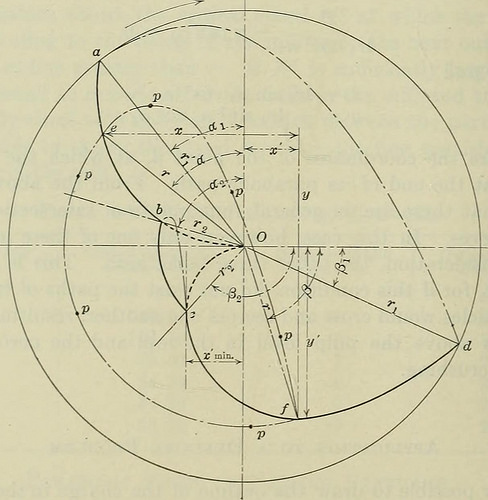
Image by Internet Archive Book Images
Identifier: transactionsmining61amer
Title: Transactions
Year: 1871 (1870s)
Authors: American Institute of Mining, Metallurgical, and Petroleum Engineers
Subjects: Mineral industries
Publisher: New York [etc.]
Contributing Library: Gerstein – University of Toronto
Digitizing Sponsor: University of Toronto
View Book Page: Book Viewer
About This Book: Catalog Entry
View All Images: All Images From Book
Click here to view book online to see this illustration in context in a browseable online version of this book.
Text Appearing Before Image:
ning at 24 r.p.m. From 1 226 X 242 X tequation (2), cos a = — ~finn – = 0.1962r, which is the equa-tion of a circle of radius „ • The center is then on the vertical axis 0.408 n units above the center of the mill. From this the value of a in Table 15 can be computed: 268 FINE CRUSHING IN BALL-MILLS Table 15.—Data for Computing Values of a r Cos a a X 4 0.7848 38° 18 6.1072 3 0.5886 53° 56 3.3624 2 0.3924 66° 54 1.1328 1 0.1962 78° 41 0.1512 0 0.0000 90° 0.0000 From the values of r and a, the curve aO, Fig. 5, can be drawn,which is the dividing line between the parabolic path and the circularpath of the particles. Then by use of equations (4) and (5) it is possibleto find any number of points on the curve cd. This may be done moresimply by drawing the circle through the point e and then measuringa distance x to a vertical line which will intersect the circle at thedesired point / as in Fig. 5. For this purpose, the corresponding valuesof x are added to the preceding table.
Text Appearing After Image:
Fig. 5 —Paths of travel of particles in an 8-ft. mill making 24 r.p.m. It is then possible to draw the line Od, which is the dividing linebetween the parabolic path and the circular path for all particles of thecharge. The complete cycle of any particle p is then seen to be from eto / along the parabolic path, and then from / to e along the circular path.From Fig. 5 it is evident that the particle p acts exactly as though itwere in a mill of radius r, the lining of which is the layer of particles ofradius next larger than r. E. W. DAVIS 269 End of the Parabolic Path Since, as has been shown, x = Ar sin a cos2 a and y = — Ar sin2 a cos a,from Fig. 5, x = Ar sin a cos2 a — r sin a,and y = Ar sin2 a cos a — r cos a. As the value of r at which a particle starts on its parabolic path andends its parabolic path is the same, then . ,, y Ar sin2 a cos a — r cos a .. _ . sin p = — = = — (4 cos3 a — 3 cos a). r r Then sin p = — cos 3a; but — cos 3a = cos (180° — 3a) and
Note About Images
Please note that these images are extracted from scanned page images that may have been digitally enhanced for readability – coloration and appearance of these illustrations may not perfectly resemble the original work.