
Check out these machining turbine wheel images:
Image from web page 512 of “The steam engine and turbine a text-book for engineering colleges” (1911)
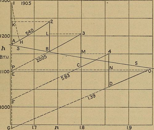
Image by Web Archive Book Pictures
Identifier: steamengineturbi01heck
Title: The steam engine and turbine a text-book for engineering colleges
Year: 1911 (1910s)
Authors: Heck, Robert Culbertson Hays, 1870-
Subjects: Steam-engines Steam-turbines
Publisher: New York, D. Van Nostrand organization
Contributing Library: The Library of Congress
Digitizing Sponsor: The Library of Congress
View Book Page: Book Viewer
About This Book: Catalog Entry
View All Pictures: All Photos From Book
Click right here to view book on-line to see this illustration in context in a browseable on the web version of this book.
Text Appearing Just before Image:
s the outcome of really complicated secondary actions,is not usefully applied in driving the rotor. (l) The Mollier Diagram. — The heat-entropy or MoUier dia-gram — see general description in § 18, web page 138 — is by far the bestscheme of representation for turbine efficiency. An illustrativeexample, worked out with data from an actual test, is diagrammed inFig. 348 and provided numerically in Table 24. The turbine has four two- §48(] TURBINE Performance. 497 impulse stages and is essentially similar to the Curtis machine in Fig. 23but it is significantly smaller and is horizontal rather of vertical. A specialfeature is the manage (by hand) of the number of nozzles open forpassage of steam in the three diaphragms amongst wheels. In Fig. 348, line lA represents adiabatic expansion in the firstnozzles and A2 shows the return at p^ of all the energy not usefullyapplied. Horizontal line 2K divides the excellent heat drop or availableenergy lA into realized output IK and return KA. The succeeding 1300
Text Appearing After Image:
Fig. 348. — Mollier Diagram from 450 Kw. 4-stage Schulz Turbine, Test 34.2in Table 20. Steam per brake horse-energy-hour, *Sh = 13.77 lb. work outputper pound of steam, W = 184.eight B.t.u. Other data, with calculated quantitiesin Table 24. stages are similarly represented by 2B3L, 3C4M, and 4D0N. Instage 1, dotted line IH shows the probable actual expansion in the noz-zle, with some loss of energy in friction, etc. it is drawn for ten per centnozzle loss, or the vertical height from A to H is one-tenth of Al. . Forthe entire expansion, IG, GO, and OP show what would be an equivalenteffect in best jet formation, heat return, and resultant efficiency: heatIP is the beneficial output and IP/IG the efficiency ratio. The values in Table 24 are all calculated from the steam tables,]3ut in sensible use of the Mollier diagram (in service type) they wouldbe found graphically. A hugely important feature of this test is the fact 498 ACTION OF THE STEAM IN THE TURBINE. [Chap. IX. that the steam is
Note About Images
Please note that these images are extracted from scanned web page photos that could have been digitally enhanced for readability – coloration and look of these illustrations could not completely resemble the original function.