Verify out these 5 axis machine shop pictures:
Image from page 266 of “American engineer and railroad journal” (1893)
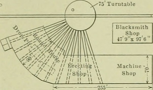
Image by Net Archive Book Pictures
Identifier: americanengineer85newy
Title: American engineer and railroad journal
Year: 1893 (1890s)
Authors:
Subjects: Railroad engineering Engineering Railroads Railroad cars
Publisher: New York : M.N. Forney
Contributing Library: Carnegie Library of Pittsburgh
Digitizing Sponsor: Lyrasis Members and Sloan Foundation
View Book Page: Book Viewer
About This Book: Catalog Entry
View All Images: All Images From Book
Click here to view book on the internet to see this illustration in context in a browseable on-line version of this book.
Text Appearing Just before Image:
months, there are about 50 engines regu-larly on this division. The hcadqtw.rters foi this energy is atCape Charles, the southern end of the road, and new shopshave just been put into operation at that po-.nt giving faeiliticsfor making all repairs, with the exception of heavy boiler w-ork,on the frequently assigned power. Although these shops arerelatively little they have been quite totally equipped with table anti placing it on any pit in the erecting shop. Althuughno crane has been installed in the machine and erecting shopat present, runways have been provided for a lo-ton crane,which will be installed later. The structure enclosing the ma-chine and erecting shop is most substantial, heavy brick wallsand steel roof trusses in a single span. A louve is supplied intlie center of the roof for the full length ot the buildnig andthe windows swing on a horizontal axis, getting controlled fromthe floor in sections by a straight push sash operator installedl)y the G. Drouve Co. 5 Turutable
Text Appearing Soon after Image:
ou[i^ tf(|r) g„d Deprcssfil Tr.trk Shop Supply GE.NERAI. Plan OF CAPE CHARLES SHOP. Coal Trestle PowerHouse modern appliances of all kinds, anci present an superb ex-ample of a appropriate and handy arrangement for ? shop ofthis size. The machine and erecting shop is enclosed in a brick Imild-ing 70 by 250 ft., and a si.x-stall section of the roundhouse formsan extension on a single finish of this developing, :S is shown in theplan. With this arrangement the five tracks in the erecting The roundhouse has a span of 90 f>. and the wooden rooftruss here emplcyed necessary the locating a row of posts 25 ft.from the outer circle. The louve in this section of the build-ing is offered with ventilators on Ijoth sides. All through thisstructure and the other folks all-natural lighting has been given carefulattention and the window region is virtually the maxmium. In themachine shop a plank floor is employed, while the erecting shop
Note About Images
Please note that these images are extracted from scanned page photos that may possibly have been digitally enhanced for readability – coloration and appearance of these illustrations might not perfectly resemble the original work.
Image from web page 304 of “American engineer and railroad journal” (1893)
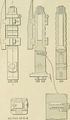
Image by World wide web Archive Book Images
Identifier: americanengineer81newy
Title: American engineer and railroad journal
Year: 1893 (1890s)
Authors:
Subjects: Railroad engineering Engineering Railroads Railroad automobiles
Publisher: New York : M.N. Forney
Contributing Library: Carnegie Library of Pittsburgh
Digitizing Sponsor: Lyrasis Members and Sloan Foundation
View Book Web page: Book Viewer
About This Book: Catalog Entry
View All Pictures: All Photos From Book
Click here to view book on the web to see this illustration in context in a browseable on the internet version of this book.
Text Appearing Prior to Image:
When big or irregular pieces are placed on the ma-chine the post is simply slipped up out of the way and can easilybe dropped back when the operate is in place. The building is clearly shown on the drawings. The upperpart or sleeve is clamped to the ram of the machine. Annulargrooves are cut on this sleeve at intervals and by signifies ofpins which pass via the clamping brackets the sleeve canbe locked in place, insuring it against the possibility of beingforced upward beneath heavy duty. The numerous annular grooveson the sleeve permit it to be closely adjusted to suit the function.By loosening the clamping bolts the sleeve can be adjusted aboutits personal axis. The clamping collar at the best prevents the toolfrom dropping in case the clamps are loosened and the pinsremoved at the identical time. The upper part of the post has a forked lower finish and a stemwhich passes by way of the sleeve and is held in spot by the nutand washer at the upper finish. The joint in between this piece and M m & V m War
Text Appearing After Image:
SECTION AT C-6 SECTION AT 5-5 TOOL POST FOR SLOTTERS. upper part, as shown. The reduce element can swing backwardslightly on the return stroke, the spring forcing it into spot assoon as the tool escapes from the operate. The tension of thespring may be adjusted to suit circumstances by implies of the screwand, if preferred, the post may be made rigid by screwing it tightlyagainst the shoulder of the reduced member. The pivot uponwhich the decrease part swings is placed to 1 side of the center AMERICAN ENGINEER AND RAILROAD JOURNAL. so that the faces of the two parts which come in make contact with whenthe tool in cutting will be of ample region. The cutting tool is held in spot by the tapered key and also, ifdesired, by the two set screws. This tool post has been in serviceat the Brightwood shops of the Large Four Railroad at Indianapo-lis, Ind., for about a year with quite effective benefits and wasdesigned and has been patented by Mr. William T. Slider, ofIndianapolis. 4-CYLINDER DEGLEHN COMPOUND JO-WHEELLOCOMOT
Note About Photos
Please note that these images are extracted from scanned page photos that might have been digitally enhanced for readability – coloration and look of these illustrations may possibly not perfectly resemble the original function.