A few nice turbine blade machining images I located:
Image from web page 412 of “Electric railway journal” (1908)
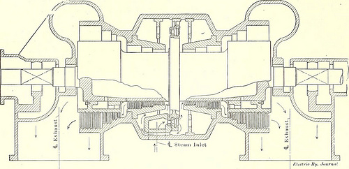
Image by Net Archive Book Photos
Identifier: electricrailway371911newy
Title: Electric railway journal
Year: 1908 (1900s)
Authors:
Subjects: Electric railroads
Publisher: [New York] McGraw Hill Pub. Co
Contributing Library: Smithsonian Libraries
Digitizing Sponsor: Smithsonian Libraries
View Book Web page: Book Viewer
About This Book: Catalog Entry
View All Images: All Images From Book
Click right here to view book on the web to see this illustration in context in a browseable online version of this book.
Text Appearing Just before Image:
rially reduce down.In consequence, the firm has placed an order for 300coasting recorders for instant delivery. These coastingrecorders are comparable to those in use on the elevated and sub-way lines of the Interborough Fast Transit Firm of NewYork, and on the Broadway automobiles of the Third Avenue Rail-road Business. The Milwaukee Electric Railway & LightCompany is the first prominent Northwestern road to inaugu-rate this program. 386 ELECTRIC RAILWAY JOURNAL Current TURBINE DEVELOPMENTS AND EFFICIENCIES [Vol. XXXVII. No. 9. In a paper read before the Engineers Society of Pennsyl-vania on Dec. 12, 1910, E. D. Dreyfus, of the WestinghouseMachine Firm, presented some fascinating information on steamturbines. Limitations in the electrical art have previouslyconfined the rotative speed of turbines inside 1800 r.p.m. forsizes above 500 kw. To-day turbines of 2500 kw are verysatisfactorily operating at 3600 r.p.m., and 4000-kw turbinesof the same rotative speed are quickly anticipated. In high-speed
Text Appearing Following Image:
60-Cycle Double-Flow Turbine work generator rotors of the through shaft type have beenlargely superseded by designs possessing the shaft bolted to theends of the field disk by indicates of a non-magnetic coupling intwo-pole machines and integral with either half of the rotorin 4-pole machines, the entire secured by bolts. The effect of rotative speed is forcibly brought out in thetable, which provides the principal dimensions on two 1000-kwturbines, 1800 r.p.m. and 3600 r.p.m. every single. Comparative Dimensions. Low Speed. High Speed, 1000-kw Turbine. 1800 r.p.m. 3600 r.p.m. Length between bearings, around…. u ft. 7^ in. 8 ft. eight in. Size of bearings, around six in. x 14 in. four in. x 9 in. Weight, like blading, approximately.. 7,000 lb. _ two,000 lb. Maximum drum diameter, approximately… three ft. 1 54 in. join. Minimum drum diameter, roughly…. 17J4 in. 10^ in. Quantity of rows of blading, approximately.. 82 49 Biggest blades (nominal heipht) four in. 4 in. Shortest blades (nominal h
Note About Pictures
Please note that these pictures are extracted from scanned page photos that may possibly have been digitally enhanced for readability – coloration and look of these illustrations may possibly not perfectly resemble the original function.
Image from web page 177 of “The street railway overview” (1891)
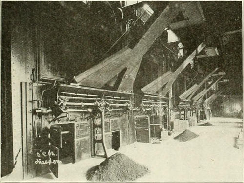
Image by Internet Archive Book Pictures
Identifier: streetrailwayrev15amer
Title: The street railway overview
Year: 1891 (1890s)
Authors: American Street Railway Association Street Railway Accountants’ Association of America American Railway, Mechanical, and Electrical Association
Subjects: Street-railroads
Publisher: Chicago : Street Railway Overview Pub. Co
Contributing Library: Carnegie Library of Pittsburgh
Digitizing Sponsor: Lyrasis Members and Sloan Foundation
View Book Web page: Book Viewer
About This Book: Catalog Entry
View All Images: All Pictures From Book
Click here to view book on the web to see this illustration in context in a browseable on-line version of this book.
Text Appearing Ahead of Image:
Principal Iliw EK Hill SE. FINCHEV KOAD SUB-STATION. by gravity to the individual stoker hoppers, getting automaticallyweighed en route by .Xvcry machines. The very same conveyor is alsoarranged to eliminate the ashes, which are discharged into a specialbin. The two feconomizers at present installed, the scrapers of whichare driven by 3-phase motors, are of the properly-recognized Green make.each possessing 1,760 tubes, 10 ft. extended and four in. in diameter. Theseare in a chamber divided into two components, each of which is providedwith its own engine-driven induced draft fan. The chimney, whichis 200 ft. higher and 15 ft. in diameter, is approached by a flue 28 ftwide, divided in two by a brick partition. En Roon The portion of the engine space actually devoted to the generatingmachinery is 233 ft. g in. long, by 43 ft, 6 in. wide at one end of
Text Appearing Following Image:
metal linings. The fle.ible claw couplings for connecting the tur-bine rotor with that of the alternator are of forged steel and run inoil, and they are arranged to let for any inexactitude in the align-ment of the two shafts. The operation of the valve gear is ideal understood by followingthe course of the steam by way of the turbine. Starting at the mainstop valve, which is of the disk sort and is operated from the plat-type by implies of gearing, the steam flows via an emergencyvalve, strainer, and double seat poppet variety governor valve, actu-ated by a centrifugal governor and steam relay, into the cylinder atihe center. It then passes by means of a series of nozzles and impulseblades and expands down to around atmospheric stress,right after which the course is by means of a quantity of pressure blades on theParsons principle to the condenser. The program of admitting steam
Note About Photos
Please note that these images are extracted from scanned page pictures that may possibly have been digitally enhanced for readability – coloration and appearance of these illustrations could not perfectly resemble the original work.
Image from page 48 of “Electrical planet” (1883)
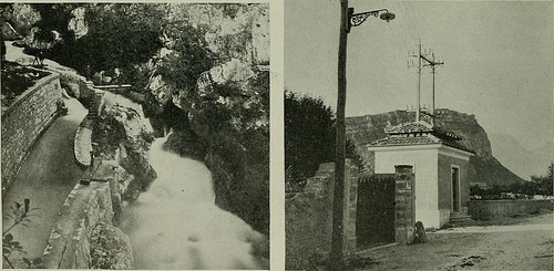
Image by World wide web Archive Book Images
Identifier: electricalworld43newy
Title: Electrical planet
Year: 1883 (1880s)
Authors:
Subjects: Electrical engineering
Publisher: [New York McGraw-Hill Pub. Co., and so forth.]
Contributing Library: Engineering – University of Toronto
Digitizing Sponsor: University of Toronto
View Book Web page: Book Viewer
About This Book: Catalog Entry
View All Photos: All Images From Book
Click right here to view book online to see this illustration in context in a browseable on-line version of this book.
Text Appearing Prior to Image:
FK. 3.—TU-NEL FIG. 5.—WIRES ON CLIFF .T G-RD. L.KE.
Text Appearing Following Image:
m.. four.—OPEN C.N.L. gates. The rods of the automatic governor arc connected with ahydraulic relay which acts upon a balance valve, hence regulating ac-cordingly the quantity of water admitted. The 300-hp turbine in theaddition is of the Rusch tjpe, the water getting admitted throughphosphor bronze passages. The blades of the turbines are Deltametal and interchangeable. Automatic regulation is accomplishedby a balance valve responding to a sensitive centrifugal governor.For the prevention of sudden jars an oil dash pot is connected withrods to the governor. The turbine is also regulated by a hand-wheel regulator, through worm and rack and pinion. For each and every ofthe machine units the automatic regulation is supplemented by a FIG. 5.—TR.VNSFORMIi^R Home. 3H in., and the armature has a diameter of 3 ft. three in. They have 18coils, two with 60 windings and the remainder with 59.five windingsof 1-6 in. wire. The 300-hp generator, also of the Oerlikon kind,has an armature diameter of 4 ft. three in., and
Note About Images
Please note that these photos are extracted from scanned web page pictures that may have been digitally enhanced for readability – coloration and look of these illustrations could not completely resemble the original operate.